• The move to the new server is done. There are some software and database maintenance updates in process. This has us passing the hat around to help out. We appreciate any donations. Seriously, even a dollar helps. The payment page may be found here - https://www.audiokarma.org/support.html

PIONEER SX-2500 FM Stereo Distortion ++

JB8

Well-Known Member
Hey Pioneer experts and enthusiasts!

I have a beautiful SX-2500 that I've grown quite fond of (damnit) shouldn't have let myself get attached but here we are...

Overview:
  • Autotune seems to work but I'm not worried about that for now
  • Has moderate ground hum, not a crazy-loud one, but annoying none the less, not a major concern, yet
  • I've recapped and replaced the 458's on the Head Amp - will replace the remaining 458's on-sight across the Control and Main Amp boards eventually
  • Replaced main filter cap (HUGE cap!) it was testing at 5400 uF so it felt like a good call to replace it
  • Will be replacing the axial 100v 100uF caps tonight, they were testing at ~230uF
  • Unit sounds fantastic when listening to source via AUX inputs - very clear, very strong, amazing sound in my opinion
  • FM has distortion when tuning in stereo stations. If you roll off the stereo signal and the dial needle goes dark the signal is clearer, but if I roll back and the light comes on, I get some increased separation, but it's distorted out there, hard left/hard right (Stereo Station and Local Station buttons have no impact on the sound)
    • I replaced the two 47uF caps on the FM IF board having read a different thread on this that they can be problematic, no change. Assuming it's one of the chips on this board? Anything else I should be checking?
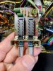
  • The High/Low Filter switch must have been bumped at some point so it has a fracture across both switch housings, the result is the low filter switch engages fine but the high switch will not engage and click in
    • Do we think this switch can be repaired or will it require replacement?
  • All switches have been thoroughly cleaned - I know cleaning is the #1 coaching given for Pioneers with some of the issues I've noted, so rest assured, I've cleaned the crap out of them
  • All but the "AM" function lights are out but all other lights are working
    • Does having burnt out function lights have an impact on the performance of the unit?
  • The signal meter is working, tuning needle is stuck and not working - it's frozen left of center
I may just end up selling the unit, but in the meantime I'm fascinated with the unit and would love to get it singing even stronger before I let it go.

Ultimately at this point my two most pressing issues are the FM stereo distortion and fixing the filter switches, so if anyone wants to chime in on any of what I'm listed please pile on. OK, I'll shut up now.

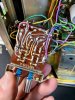
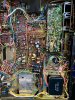
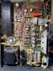
IMG_0494.jpg IMG_0495.jpg IMG_0496.jpgIMG_0497.jpg IMG_0498.jpg
 
Register to hide this ad
I currently have an SX-2500 on my bench also but can only offer minor help.
The bad function lights aren't causing your problem. I only had PHONO and AM lights working, nothing else, and my FM stereo worked great. My auto tune did not work and I hoped new function lights would fix it but it didn't. So far, I have recapped all of the power supply, auto tune board and the main amp unit. MOST capacitors were out of spec uF wise and several had high ESR, like 5 ohms. *****So I recommend you recap the FM related boards.*****

The 5 indicator bulbs originally are 8v 50mA and measure 5mm dia by about 13mm long. I installed LED bulbs and they work without issue except for being a bit bright. I should have put higher ohm resistors in series with the LED's but it's good enough.
All 3 of my auto tune lamps were dead and my FM stereo worked fine FYI.
I am going to create a new Pioneer post on re-lamping the SX2500.
Jef
 
Thanks, Jef, I appreciate your input here. The function lights were a long shot so I'm glad you could confirm that's likely not the issue with the FM distortion. I'll get cracking on the rest of the FM boards caps and see how I fair. Excited to check out your post on the re-lamping. I've had good success across several brands and models specific to this process, but this guy seems to be more of a fortress when it comes to accessing the function lamps, please let me know when the post is up.

Specific to the filter switch, I imagine I can just attempt to super glue the switches after thoroughly cleaning the junction points with some acetone, doubtful there would be a replacement available anytime soon.

Does your unit have much of a ground hum?

Btw, when I first got the unit and tested the Auto Tune the tuner would just amble along, never stopping on any stations. It would go from one end to the other repeatedly and the only way to get it to stop was to power down the unit. I then figured out how the two push buttons and FM Muting worked and got it to stop on stations. I'm honestly not really too fixated on the Auto Tune and would really just love to get rid of the distortion, fix the switch and reduce the ground hum.

I'll let you know how it goes, thanks again!
 
My unit does not have any hum. There is a fair amount of chatter out there in google-land about the 2500 having hum issues and many suggestions say to verify good circuit grounds. The individual boards have chassis ground connections which need to be checked. Zero out your ohm meter leads....take your ohm meter and touch the leads together and note the meter reading. If it is something like .2 for example then you'd expect a ground point on a board to chassis reading to be .2 to .3 ohms. Reference the schematics to verify each ckt board grounds are very close to 0.0 ohms of resistance.

As to the FM issue, verify all power supply voltages match reasonable well to the schematic values. My power supply board actual voltages match very close to whats shown on the schematic. Also verify all your FM related boards are getting the correct voltages.

Might as well try and fix the cracked switch. If it's a no go then figure out the pioneer part number. Other Pioneer models may use the same part number switch. Look at early 70's Pioneer models that have push button switches to see if they have the same part number. Then search ebay.

I created an SX-2500 lamp thread yesterday and will be improving on it over the next week or so.
Jef
 
  • Like
Reactions: JB8
Thank you, Jef, great stuff here! I'll do some probing to check the ground points and voltages, appreciate the way you laid that out. Specific to the switch, I repaired it and it seems to be working at about 75%, which is fine for now.

Excited to check out that thread you're working on!

Thanks again for your help here, I'll let you know how it goes.
 
I will be watching your progress!
These are quality built receivers even compared to my later SX-750. I recently bought a near mint SX-9000 (has reverb) which looks much like the 2500. It's next.

Here is my SX-2500 lamp/bulb thread:
https://audiokarma.org/forums/index.php?threads/pioneer-sx-2500-bulb-lamp-information.992141/

The 5 function indicator bulbs are a bitch to get to. But it's gotta be done.
It will be real easy to cut or melt the dial cord. Have spare .030 on hand.......

An FYI....I will be creating a thread with info and pic's on the auto tune motor and gear box issue I had.
 
Checked PS DC voltages and may have found part of the hum issue (schematic value):

B1 23V (22V)
B2 -4.81V (-5V)
B3 12.33V (12V)
B4 12.81V (13V)
B5 25.31V (25V)
B6 OL (85V)
B7 OL (32V) (coming from main filter cap, which has been replaced)

Assuming these numbers indicate some bad transistors? Amazing that the signal sounds as good as it does via the AUX channel if if have significant issues with the PS. I'll do some additional testing then start pulling components as necessary to test them properly. Oh, and when I turned the unit on this morning the auto tune just took off on it's own, back and forth, never stopping on any known strongish stations - good times, ha!

And thanks for the bulb thread link, gonna check it out now!

Lastly, I too have an SX-9000 waiting for some attention, my son calls it "the big boy". Very cool unit indeed.
 
My PS board voltages:
B1 22.27v
B2 -5.03v
B3 12.50v
B4 13.31v
B5 26.56v
B6. 88.5v
B7. 93.0v

Minor, but you have a typo in yours; B7 expected volts is 92 not 32.

I don't understand the OL indications....do you have your meter in manual range instead of autorange? Than would give an over range indication.
You unit wouldn't work without reasonable B6 and B7 voltages since they feed the main amp it's juice.
Check your voltmeter......... not transistors.......

I just today, minutes ago, adjusted the "1/2 voltages" and set the output bias for 10mV across the emitter resistors so I should be loading the power supply correctly. So my voltages are good.

Edit: lets wrap that up and get to the 9000's!
 
  • Like
Reactions: JB8
Thanks for the feedback on B7 value, my schematic is hard to read. For the DMM I've got it in the mode I typically have been using for DC voltages, but I could be using this thing wrong. Just last week I realized I'd been checking AC voltage in the A~ HZ range instead of V~, so I'm sure I could be off here as well. It would be a great relief to know it was just user error, I started to disassemble the main amp unit just to get a look at the other side of the board and quickly retreated when I found it incredibly difficult to access.

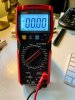
Here's what setting I had my DMM on:

IMG_0504.jpg IMG_0506.jpg
 
Something you can do to track down that hum is use the pre-out/main-in separate switch on the back. Then use a different preamp to feed the SX-2500 main amp. Or feed the SX-2500 preamp into a different amp.
It'd be a great help to know if your preamp or main amp is the hum source.
 
  • Like
Reactions: JB8
On that meter.....before you take a voltage reading it will display something like 0.00.
Then, if it is on manual range it will display OL when the voltage is above the manual range selected.
My thinking anyway. Makes sense. I am looking at the manual for it.......

That amp board comes out pretty easy really. I was scared at first.
With the unit upside down, you remove 2 chassis mounting screws from each side of the whole assembly. Then lift the entire heatsink/board assembly up and tilt toward the front of the unit. First take pictures of all the wire connections cause you will likely break off a wire wrap.
 
  • Like
Reactions: JB8
There is no auto/manual button because you must select the appropriate range of voltage with the selector knob.
In the pic you posted it will only read up to 60v. Flip it to the 600v range.
 
Last edited:
  • Like
Reactions: JB8
It has a very handy feature (actually many) called "REL".
It is the yellow button labeled "SEL/REL".
Read the top right corner of the instructions. REL can be used to subtract the lead resistance to get a more accurate low ohms reading, like when tracing out grounds we talked about earlier.
 
  • Like
Reactions: JB8
I have my unit about half re-capped. The power supply, main amp board with new outputs, auto tune board, and the two output coupling caps - all.
Power supply voltages are good. Bias is set. It sounds really good! Time to go inside with it connect to some better speakers! I used some 4700 uf output caps I had on hand to replace the original 2200uF's. I put a 10,000uF main filter cap in it v.s. the 4700uF original (It was a perfect fit physically). Wasn't sure if it would blow the fuse or fry the rectifier diodes but so far it's good.

I also put a relay in for power up to take the current load off the power switch. I will do a post on that soon.
 
Wow, great stuff, @1rebmem , really appreciate the information, on everything!

I think I'll first try to figure out the FM distortion, then track down the hum, then replace the lights, then on to the 9000! Well, maybe, but it will be on the bench sometime in the near future for sure.

I'll dig in some and let you know how I'm fairing. And now that I know more about my DMM - thanks to you - I'll recheck a bunch of the voltages and report back on my findings. Oh, lastly - and I suppose this is a great lesson for those tuning in to this thread - if you have a DMM, and you have the manual, READ the manual, ha!

Thanks again!
 
OP......
Yesterday I replaced the electrolytic cap's on the FM boards and MPX board.
All were high out tolerance and had high ESR, up to 7 ohms.
My FM is now better in every way. It surprised me with the improvement.
 
  • Like
Reactions: JB8
Thanks for the update and encouragement, I've got to get back in there and tackle my FM and MPX boards as well. I snuck in some quick work on an HK 430 but have plans to circle back to my 2500 ASAP!
 
Back
Top Bottom