• The move to the new server is done. There are some software and database maintenance updates in process. This has us passing the hat around to help out. We appreciate any donations. Seriously, even a dollar helps. The payment page may be found here - https://www.audiokarma.org/support.html

Pioneer sx-3700 protection relay issue

Ajp1992

New Member
Hey all, long time listener, first time caller
Long story short: I’m fairly inexperienced and trying to restore an sx-3700. I’ve found some really helpful info but I’ve hit a dead end, unless I’m missing something, hope im not being redundant here.
The unit powers on and everything lights up but the relay doesn’t click on. I’ve followed instructions on a previous thread and checked the test pins (tp 46-47 and tp 48-49) with satisfactory results. Then checked the power supply and everything checked out there. The next step for the OP of that particular thread was to check DC balance at the Henry coils labeled L1 and L2. That’s where my problem is. I’m assuming the Henry coils are the open copper coils right next to the large heat sink (on the side closest to the faceplate). Am I right in assuming that? With the receiver powered on I am getting -24mv at both leads of each coil, my understanding is that it should be close to 0v. Where do I go from here? Thanks in advance for any information
 
Register to hide this ad
With the black DMM probe on the chassis ground. Probe the Henry coil and you should get a millivolt reading on either coil. If the voltage is over a volt something is wrong.
If both channels are reading the same (-24v like you say) then the power supply is probably at fault.
If the reading is in the negative voltage then the amps are missing the positive voltage from the power supply.
Check the voltages at the big filters. There should be +-41 volts. One side positive +41v the other negative -41v's.
Do this voltage check on the DBT with the controls centered and the volume at min. Nothing connected. This only necessary in case you slip and short something out.

These receivers are fragile in that amp components are hard to come by. So lets see if it can be brought back to life. Once its up and running, you can do a complete service so it will stay there.

I forgot to welcome you to AK.
Welcome.
 
Last edited:
Thanks for the response, so I’ve checked the voltages on the big filters. Again I am new to electronics so bear with my incompetence but I am an electrician by trade so I’m no stranger to a DMM. These big polarized capacitors seem to have 3 leads, until I learn what they are I will call one marked on the cap with the negative strip “negative”, the one directly across from it “positive” and the third one I shall call “the third lead” ‍♂️. I’ll also refer to the capacitor closest to the transformer the “bottom” and the other one the “top”. I will build a DBT tonight before a go any further but here are the readings I got;

Bottom capacitor
Negative lead -4.4mv
Positive lead 41.5v
3rd lead .4v

Top capacitor
Negative lead -42.1v
Positive lead -4.5mv
3rd lead -39v

I hope that makes sense, thanks again
 
Look at the schematic.
Hifi engine.com has the service manual. Free, safe site with sign-in.
Your going to have to access the power supply board and look at Q17. It may of desoldered it self. It's in charge of the +38v's your missing.
Good job finding and reporting.
If you want to begin digging in. Look at the arrangement of the boards and heatsink. Never remove any wires from the boards. Loosen the harness to get any assess you need.
It's been awhile a 3700 been on the bench but I think you can remove the amp board and then the heatsink and outputs as an assembly(?). That might help access to the power supply.
Take your time and take images before you begin. You may have this fixed before the night is over. Remember, it's the journey when it comes to fixing these pieces.
 
So I’m having a bit of trouble following the schematic, but I believe I found Q17 (a transistor mounted to a small heat sink near to those big filter caps) it tested fine according the the voltages in the schematic. It seems to me that the only component between that 39v coming out of q17 and the filter lead missing 39v is C103, a 50v 100uf capacitor. Could that be my problem or am I not understanding correctly?
 
I'm having trouble visualizing the caps and circuit. I can't find any images to go by.
You would be looking at Q17 and C104. D18 the zener diode and a few resistors. You are missing the plus side of the regulated. C103 and Q18 are the negative side.
Look at the backside of the board for any visual clues.
 
I was confused about the 24 mV vs. 24 volts. If it is 24 mV, then it's not a problem.
Although the voltage on Q17 is a common issue, if you are getting around 27 volts on the output (emitter) then the regulated supply is not an issue. The regulated voltage affects sound, but not the relay control circuit.

.5 amp fuse FU21 feeds the protect circuit. Check anode of D16. IF no voltage, fuse probably blown. IF around 34 volts, fuse is okay. If about 20 volts then Cap c116 (47uF 50V) is probably open. The fuse is on an AC line, so no DC voltages will be on the fuse.

If the 34 volts for the relay circuit is there, and the voltages on the "henry" coils are less than +- 1 volt, I'd be checking voltages around Q25 and see which way it indicates to continue trouble shooting.
There also are a couple of jumpers and thin traces on the grounds and power leads, so be aware if voltages are missing that it can be a dry solder or cracked trace, but not too likely....
 
fwiw, the 3rd lead on a single section cap (which is all the 3700 has), is just a stabilizer, keep something big from putting strain on thin copper traces
 
Alright then it seems I may have misunderstood my initial readings and sent @zebulon1 down the wrong rabbit hole, sorry about that. So I seem to have 34v getting to my relay and the Henry coils are reading about 0.2v. I am really having a hard time with this schematic and it is quite frustrating, I can’t seem to find q25 but I guess that’s my next move. It seems like have to learn a bit more about reading these schematics and I might be at a stand still until then.
 
No worries.
.200v is too high for a DC Balance (offset).
I would like to see a better voltage reading of both channels, and see it to the micro volt resolution.
The offset should be down to the .055v range or lower.
 
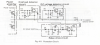
So upon further inspection of the service Manual I’ve come across the PCB connection diagram, who knew?, which is much easier for me to follow. I figured I’d start at the power supply circuit and work my way out from there. Already I’ve noticed a funky reading from Q20. Q17, 18, and 19 checked out fine (all spot on or within 1 volt or so) except for the C pin of Q20, it’s supposed to read 9v but I’m getting 25.9v. Any suggestions? Thanks again for all of your help everyone
 
So upon further inspection of the service Manual I’ve come across the PCB connection diagram, who knew?, which is much easier for me to follow. I figured I’d start at the power supply circuit and work my way out from there. Already I’ve noticed a funky reading from Q20. Q17, 18, and 19 checked out fine (all spot on or within 1 volt or so) except for the C pin of Q20, it’s supposed to read 9v but I’m getting 25.9v. Any suggestions? Thanks again for all of your help everyone
It appears (to me) that the C voltage on Q20 depends on the current - if you assume the 90 mA the schematic shows, then the 25.9 volts is OK. The voltage will vary with load, (looks like the selector lamps but ???) so I don't think you have anything to worry about here.

You should be going back to the protect circuit. There is a description in section 4.8 of the manual, but they use different part numbers in there descriptions and diagrams. Q3 should be Q21 (left channel) or Q22 (right channel) for overload part. Q4 and Q5 should be Q23 and Q24. Q6 should be Q25. D6 should be D20.

Look for .6 volts on the base of Q25. IF .6 or higher, then Q25 probably open. If less, see if 15 volts on the other side of D20. If a lot higher, then D20 is open or somebody put a regular diode instead of a Zener. If lower, then it is probably being pulled down by one of the overload transistors. (Q21 or Q22). If okay, problem is probably in the DC detect circuit (Q23 and Q24) Also check R12 (560 ohm 2W) (R9 in the diagram) If that is open, no relay.

upload_2020-5-18_7-11-43.png
 
So I’m only getting 0.03v at the base of Q25 and 0.75v on the other side of D20. What should I be looking for at Q21 and Q22?
 
So I’m only getting 0.03v at the base of Q25 and 0.75v on the other side of D20. What should I be looking for at Q21 and Q22?
Yes, but you should first check the emitter resistors (0.22 ohms) r333 and r336. Since they are .22, you meter may read them higher as this is near what the meter leads add. Check all four - the circuit is activated by excess voltage across the resistors - so if one were open, get high voltage drop. It is a little weird checking voltages, as they are referred to the output voltage and will float from ground, but looks like it takes about a volt drop across one (5 amps) to shut off the relays. Resistors this low can be check in circuit.
The channel can be isolated by removing one leg of the diodes D14 and 15.
 
So just to be sure, you are suggesting that I remove one leg of both D14 and D15, then check resistance across R333, R334, R335, and R336?
 
So just to be sure, you are suggesting that I remove one leg of both D14 and D15, then check resistance across R333, R334, R335, and R336?

Well, check the resistors first, then if all okay, lift the legs (one at a time) on the diodes and see if the relay clicks. You can check the transistors to see if one is shorted CE before lifting diodes too.
 
Well, check the resistors first, then if all okay, lift the legs (one at a time) on the diodes and see if the relay clicks. You can check the transistors to see if one is shorted CE before lifting diodes too.
Testing doesn't have to be done in any particular order - however checking the transistors for shorts and emitters for open can be done in circuit and in very little time, so smart thing is to do those first....
 
So I can’t seem to procure a reading on any of the emitter resistors for some reason. I’ve checked some bigger ones just to see that my meter is working correctly with good results. Maybe they’re too small for my meter to pick up? I definitely have a CE short in Q21. No other shorts that I found. Should I replace that before moving any further? Are those somewhat easily available?
 
Back
Top Bottom