• The move to the new server is done. There are some software and database maintenance updates in process. This has us passing the hat around to help out. We appreciate any donations. Seriously, even a dollar helps. The payment page may be found here - https://www.audiokarma.org/support.html

Pioneer SX-5580 Voltage Mod?

kdris10

Active Member
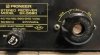
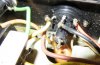
Hiya, I have come across an ok 5580, European model.While looking at the rear panel it has the multi voltage selector switch, but also has an installed normal fuse housing with a 10amp fuse in the socket. I noticed with the bottom cover off two wires were removed from the original multi voltage selector switch and soldered to the new fuse assembly. Also you cannot unscrew the screw out of the multi voltage switch as it is sort of like a flat plug with nothing to unscrew. I will only be using this at 120V, and the manual states a 10amp fuse is the way to go for that voltage. The unit works without issue, bias and offset look very good. I have attached a few pictures of the wiring to make sure this doesn't burn the house down. The experts could hopefully let me know if this is a good fix or should I keep an extinguisher handy?

Brown wire leads to AC outlets on the rear panel, the green wire leads to the surge current suppressor AWX-098 pin 5 (120V)

Thank You.
 

Attachments

  • IMG_1842.jpg
    IMG_1842.jpg
    49.6 KB · Views: 42
  • IMG_1849.jpg
    IMG_1849.jpg
    51.8 KB · Views: 40
  • IMG_1844.jpg
    IMG_1844.jpg
    70.7 KB · Views: 40
  • IMG_1850.jpg
    IMG_1850.jpg
    75.7 KB · Views: 36
  • IMG_1852.jpg
    IMG_1852.jpg
    33.3 KB · Views: 37
Last edited:
Register to hide this ad
Perhaps the center cap for the voltage switch was lost at some point. This cap retains the fuse, so they added an auxiliary fuse holder. I can't tell if that center is still live or not. I hope not. I would still put some kind of plastic plug over the center hole.
 

Attachments

  • Pioneer Voltage Selector.jpg
    Pioneer Voltage Selector.jpg
    116.8 KB · Views: 22
Perhaps the center cap for the voltage switch was lost at some point. This cap retains the fuse, so they added an auxiliary fuse holder. I can't tell if that center is still live or not. I hope not. I would still put some kind of plastic plug over the center hole.

Thanks for the reply, if you look at the 3rd picture you can see that wiring was removed from the center lead inside the receiver.
 
It probably got melted by someone putting a big amp fuse in it (Trying to jump start it after a blow out). had to use a stand alone setup as a replacement. Check out the amp boards for any signs of repairs.
 
Just trying to find out if this a safe fix, also if I were to aquire a new multi voltage selector where would these two wires solder to.

Thanks
 
You're going to have a extra hole in the back. I'd leave it. Most will not notice it.
 
Just trying to find out if this a safe fix, also if I were to aquire a new multi voltage selector where would these two wires solder to.

Thanks

I understand but is this a safe fix? I'm concerned about an electronic issue, is this fix safe to use without worrying about an eventual burning down of my house.
 
If you are using the correct value fuse and it's running you should be good. The work looks ok and the wire connections have good clean solder bonds. Look for any wire routings that might cause issues but from the images it seemed good.

If replacing it the wires from the retrofit holder: The wires from replacement holder would get wire wrapped to the two pins at the center of the assembly. The two pins that are missing the wires on the original voltage selector.
 
Last edited:
If you are using the correct value fuse and it's running you should be good. The work looks ok and the wire connections have good clean solder bonds. Look for any wire routings that might cause issues but from the images it seemed good.

If replacing it the wires from the retrofit holder: The wires from replacement holder would get wire wrapped to the two pins at the center of the assembly. The two pins that are missing the wires on the original voltage selector.

Thanks sir!, I might replace the old multi voltage switch with one from a parts unit I have. Do you think JB weld and some black paint might take care of the hole from the newer fuse holder?

Thank You
 
There are lots of options to cleanly cover a hole. Google image search for "snap style hole cover".
 
Thanks sir!, I might replace the old multi voltage switch with one from a parts unit I have. Do you think JB weld and some black paint might take care of the hole from the newer fuse holder?

Thank You

Check using parts.pioneerelectronics.com to be sure the original and the replacement are the same thing. There ARE several different voltage selector switches in the line-up.

UNLESS the parts unit is the same model, but then you wouldn't have asked where the extra wires solder to. You would just have looked and compared.

THAT (where wires) also needs some exploration, just to be sure. Zeb's pat answer doesn't cover it all. Adding a retrofit fuse holder implies adding at least one wire, to get the power over from the old selector TO the retrofit holder, the original exit wire from the original selector/fuse would be moved to the retrofit fuse and perhaps extended to reach.
 
Check using parts.pioneerelectronics.com to be sure the original and the replacement are the same thing. There ARE several different voltage selector switches in the line-up.

UNLESS the parts unit is the same model, but then you wouldn't have asked where the extra wires solder to. You would just have looked and compared.

THAT (where wires) also needs some exploration, just to be sure. Zeb's pat answer doesn't cover it all. Adding a retrofit fuse holder implies adding at least one wire, to get the power over from the old selector TO the retrofit holder, the original exit wire from the original selector/fuse would be moved to the retrofit fuse and perhaps extended to reach.

Hi Mark, yes I looked and the multi selector voltage switch is common on the 1050-950-850-750, Also I'm thinking the green wire was added later, it looks like a newer wire and it's extended from the soft start board to the fuse housing in a straight line, which looks a little weird to me. Can you shed some light on what wires get soldered to the center legs on the new multi switch, I cant find a schematic with this multi switch.

Thank You
 
The 1250 (S-Model) also uses the AKR-031. At the end of the 1250 manual there is a schematic with the 4 way switch. HOWEVER, I would hold off on using it until Mark says it's ok to use. The 1050 and 1250 have that Surge suppressor (delay start up ) in the power supply and wiring it up wrong can lead to problems and or a 55+# doorstop.

Once you get it all straightened out, recommend you switch it to 120V operation so you aren't straining the transformer and other parts. With it now @ 110V it's overloading the windings some, and the downside parts see higher voltages which aren't good for them. With it @ 120v it'll be more in line with todays voltage, although still behind the curve a little. But not enough to hurt .
 
The 1250 (S-Model) also uses the AKR-031. At the end of the 1250 manual there is a schematic with the 4 way switch. HOWEVER, I would hold off on using it until Mark says it's ok to use. The 1050 and 1250 have that Surge suppressor (delay start up ) in the power supply and wiring it up wrong can lead to problems and or a 55+# doorstop.

Once you get it all straightened out, recommend you switch it to 120V operation so you aren't straining the transformer and other parts. With it now @ 110V it's overloading the windings some, and the downside parts see higher voltages which aren't good for them. With it @ 120v it'll be more in line with todays voltage, although still behind the curve a little. But not enough to hurt .


Hi Mark, sorry to hear about your loss, my Mom is 84 and has Pneumonia as I write this. Hopefully she will be OK, time heals all wounds.

What do you think about Larry's comments above, can I go ahead and change it out to the multi switch voltage selector from the SX-750? Also if you look at my pictures, what wires would I connect to the two center legs of the new switch?
Thanks, God bless you and your family, and take care of yourself.
 
Back
Top Bottom