• The move to the new server is done. There are some software and database maintenance updates in process. This has us passing the hat around to help out. We appreciate any donations. Seriously, even a dollar helps. The payment page may be found here - https://www.audiokarma.org/support.html

Pioneer SX-636 recap power supply question

mstewart

Active Member
Hello, I recently began a recap of my SX-636. I just started working on the power supply which has been recapped with the transistors replaced. I have not changed any diodes. Before I move forward I started measuring voltages and am comparing them to the service manual.

Everything is checking within 1v of the manual with the exception of pin 14. Instead getting 6v I am getting about 13.5 v...the same number I am getting on pin 13. What I can see is that there's a 270 ohm resistor that is between pins 12,13 and 14. So I pulled it just to make sure it checked out and it was fine. So with my limited understanding I'm sort of scratching my head wondering why I'm not getting the 6v at pin 14?
 
Register to hide this ad
Pin 14 drives the Stereo Indicator lamp. When the lamp is off, there will not be any current drawn from pin 14 and as a result, there will be no voltage dropped across the 270 ohm resistor. Once the lamp is turned on, it will draw roughly 30mA which should drop the pin 14 voltage from 13.5V to 6V.
 
Pin 14 drives the Stereo Indicator lamp. When the lamp is off, there will not be any current drawn from pin 14 and as a result, there will be no voltage dropped across the 270 ohm resistor. Once the lamp is turned on, it will draw roughly 30mA which should drop the pin 14 voltage from 13.5V to 6V.
Thank you for the explanation.
 
I came up with another question. I don't want to start a whole thread about it if I don't have to.

On the power amp, C9 and C10 are listed as being 47uf 35v. So that's what I bought. But as I was about to remove them I found the caps on the amp are 47uf 50v. So my question is do I need to replace those with the same voltage rating? Or can I use the ones I have? I don't know if the people in the Pioneer factory were known to install caps with a different voltage because they had them on hand or if that was an intentional change.
 
The 47uf/50V is probably more about safety should power supply Q1 fail c-e short. Also a bit difficult to say what happens
during power up/transients. Service manual shows 14.4V during steady state. Part of the motive for recapping is piece of mind
so replace with the 50V item and not worry about "burning down the house". Also useful lesson, work of what's installed in the
amp rather than the service manual, too many late production changes.
 
The 47uf/50V is probably more about safety should power supply Q1 fail c-e short. Also a bit difficult to say what happens
during power up/transients. Service manual shows 14.4V during steady state. Part of the motive for recapping is piece of mind
so replace with the 50V item and not worry about "burning down the house". Also useful lesson, work of what's installed in the
amp rather than the service manual, too many late production changes.
I've heard it said many times to stick with the microfarad rating of a cap if it's different than the manual. Wasn't sure about voltage though. Thanks
 
Pioneer on ocassion upped the voltage on caps, when they ran low of a certain cap. No harm, no foul. It ties in with the disclaimer " We reserve the right to make un-announced changes in circuitry and parts as needed", or words to that effect. With todays higher line voltages, and pioneers propensity of installing caps that were rated for a couple of volts higher than the circuit produced, installing a cap with the next higher voltage is a smart move. FOR EXAMPLE: A 50V cap in a 49V circuit leaves ZERO headroom in todays world with old designs. A 63V cap would have a better chance of surviving transients. Pioneer did this a lot, if they had stock of a larger cap already paid for and the correct cap in quantity was more $$, they went with the stuff onhand.
 
I think that's an interesting discovery.
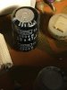
I have a "spare" untouched SX-636 here, so I got it down to see what's in it for C9 and C10.
IMG_2147.JPG

Its SN is VK so November 1975.
The manual's parts list and the schematic certainly do say 35v.
 
Pioneer on ocassion upped the voltage on caps, when they ran low of a certain cap. No harm, no foul. It ties in with the disclaimer " We reserve the right to make un-announced changes in circuitry and parts as needed", or words to that effect. With todays higher line voltages, and pioneers propensity of installing caps that were rated for a couple of volts higher than the circuit produced, installing a cap with the next higher voltage is a smart move. FOR EXAMPLE: A 50V cap in a 49V circuit leaves ZERO headroom in todays world with old designs. A 63V cap would have a better chance of surviving transients. Pioneer did this a lot, if they had stock of a larger cap already paid for and the correct cap in quantity was more $$, they went with the stuff onhand.
Understood. That makes me wonder when increasing the voltage of a cap, how much is too much? For example installing a 100v cap where it should be 25v?
 
35V go to 50max
I usually don't take them more than 1 or 2 voltage levels. For a 35V cap no higher than 63V. The data sheets will have all the voltages and values for a particular series of cap.
 
35V go to 50max
I usually don't take them more than 1 or 2 voltage levels. For a 35V cap no higher than 63V. The data sheets will have all the voltages and values for a particular series of cap.
Thanks that will help a lot going forward.
 
Last edited:
Back
Top Bottom