• The move to the new server is done. There are some software and database maintenance updates in process. This has us passing the hat around to help out. We appreciate any donations. Seriously, even a dollar helps. The payment page may be found here - https://www.audiokarma.org/support.html

Pioneer sx-680 right meter spikes, large pop in speaker

There’s two.
I saw the one from the volume pot but discounted it. There’s no power - although, have you tried other inputs. Like the Aux with a CD player. Maybe the AM/FM tuner is sending voltage through the pre?
Try the tuner with a meter connected to the cap down stream from the volume pot. See if you can see that voltage spike.
It’s my Friday night and I’m watching the Thursday night game. :confused:
I’ll be around all day tomorrow, checking in. I’ll have the schematic near by.
 
There’s two.
I saw the one from the volume pot but discounted it. There’s no power - although, have you tried other inputs. Like the Aux with a CD player. Maybe the AM/FM tuner is sending voltage through the pre?
Try the tuner with a meter connected to the cap down stream from the volume pot. See if you can see that voltage spike.
It’s my Friday night and I’m watching the Thursday night game. :confused:
I’ll be around all day tomorrow, checking in. I’ll have the schematic near by.

I have tested all the inputs buy using them with CD player in aux, turntable in phono, 8-track player in tape monitor. I'll check the cap down steam from volume. Enjoy the game. I'm watching it too rooting for the cardinals
 
Packers won ;)
Check voltage at the diode D503 and check the diode for serviceability.
With the C302 still only removed, (The coupling cap first removed. Separating the pre from the amp). Check for DC voltage at the pre-amp side of the cap. Clip to the JFET source side and look for the voltage spike we saw at the STK module.
We better make sure its coming from the pre-amp.
Then look for the spike voltage at C508. you don't have to remove it.
 
Packers won ;)
Check voltage at the diode D503 and check the diode for serviceability.
With the C302 still only removed, (The coupling cap first removed. Separating the pre from the amp). Check for DC voltage at the pre-amp side of the cap. Clip to the JFET source side and look for the voltage spike we saw at the STK module.
We better make sure its coming from the pre-amp.
Then look for the spike voltage at C508. you don't have to remove it.

Hahaha I'm a lions fans so I gotta root against the packers lol. I started a Facebook group called "the nfc north trash talk group". I'll send u a link to join if you do facebook groups. Good game last night tho . I'll check this stuff u just posted when I get home today. Thx bud

https://www.facebook.com/groups/593534168167421/
 
So I cant find C508 to check for a spiked voltage cause I cant make the number out on the print. I checked Diode D503 and got 0.6 VDC. I removed C302 coupling cap and the voltage at the pre-amp side was 80 - 82 vdc. I check it a few times that's why the range of volts. I checked the JFET - 2SK117 source pin and normal on volts was 1.9Mv. If I turned it on or change inputs it spikes to 192Mv befor dropping back down to 1.9Mv. I checked the voltage at the cap downstream from volume and it was 4.6v & no spike
 
C508 should be near the far right end of the board, as viewed from the top. It's right behind the loudness switch.
 
I still cant find C508 on the schematic. I couldn't find the loudness button for reference on the schematic either. The loudness is S5, I found S1-S9 bit no S5
 
could try balance to left vol to min and see if less of a spike .. also clean the rec switch which might be leaking .

One I put back the coupling cap between preamp and main amp then I can test with balance to the left and vol at min. Not sure where the rec switch is
 
The evidence I am seeing here all points to the right channel muting circuit (Q504) not muting correctly. When the Function (input) switch is switched between inputs the muting circuit is activated briefly (through Q501) to stop switching noise. If the left channel is working correctly the muting function is working correctly up to the cathodes of D503 and D504. Since you have eliminated the power amp section by pulling the coupling cap (C302) and are not seeing the spike before the muting circuit (at C508) the spike is originating in the muting circuit. Compare DC voltage between - side of C301 (left) and - side of C302 (right). They should be about 0vdc. The same should be true for the - side of C512 (right) compared to the - side of C511 (left), about 0vdc. Look at the - side of C512, and the - side of C302 while moving the Function switch. You should not get a spike there. If you do get a spike at either or both of those places, you have a blown FET (Q504). It is allowing the negative 'muting' spike that should be squeezing off the FET channel to pass into the audio path.
 
The evidence I am seeing here all points to the right channel muting circuit (Q504) not muting correctly. When the Function (input) switch is switched between inputs the muting circuit is activated briefly (through Q501) to stop switching noise. If the left channel is working correctly the muting function is working correctly up to the cathodes of D503 and D504. Since you have eliminated the power amp section by pulling the coupling cap (C302) and are not seeing the spike before the muting circuit (at C508) the spike is originating in the muting circuit. Compare DC voltage between - side of C301 (left) and - side of C302 (right). They should be about 0vdc. The same should be true for the - side of C512 (right) compared to the - side of C511 (left), about 0vdc. Look at the - side of C512, and the - side of C302 while moving the Function switch. You should not get a spike there. If you do get a spike at either or both of those places, you have a blown FET (Q504). It is allowing the negative 'muting' spike that should be squeezing off the FET channel to pass into the audio path.

Thx so much for the info. I appreciate it. I'll post the results as soon as I get them
 
The evidence I am seeing here all points to the right channel muting circuit (Q504) not muting correctly. When the Function (input) switch is switched between inputs the muting circuit is activated briefly (through Q501) to stop switching noise. If the left channel is working correctly the muting function is working correctly up to the cathodes of D503 and D504. Since you have eliminated the power amp section by pulling the coupling cap (C302) and are not seeing the spike before the muting circuit (at C508) the spike is originating in the muting circuit. Compare DC voltage between - side of C301 (left) and - side of C302 (right). They should be about 0vdc. The same should be true for the - side of C512 (right) compared to the - side of C511 (left), about 0vdc. Look at the - side of C512, and the - side of C302 while moving the Function switch. You should not get a spike there. If you do get a spike at either or both of those places, you have a blown FET (Q504). It is allowing the negative 'muting' spike that should be squeezing off the FET channel to pass into the audio path.

So I wasn't sure exactly how u wanted me to test and compare C301 & C302 so I took different readings.
C301: Terminal to terminal=76.2Mv
+ terminal to ground=1.5 thru 2.0Mv
- terminal to ground=81.2Mv

C302:Terminal to terminal=70.8Mv
+ terminal to ground=1.5 thru 2.2Mv
- terminal to ground=75.4Mv

I checked C302 for a spike while changing input mode. I put + lead to + terminal and put - lead to - terminal and set meter to Mv DC and it did not spike. I couldn't find C512 to check for spike while changing input.
 
I was not clear enough, black lead to chassis ground for all specified measurements. Measure with red lead on dc volts range.
Check at the cathode of D504 for the mute switching signal while changing the Function switch.
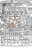
C512 is in the middle of the orange box, near pins 43, 44, 45, 51. Next to the FET.

upload_2021-11-4_19-57-22.png

This image was taken from the service manual page 21.
 
Last edited:
I was not clear enough, black lead to chassis ground for all specified measurements. Measure with red lead on dc volts range.
Check at the cathode of D504 for the mute switching signal while changing the Function switch.
C512 is in the middle of the orange box, near pins 43, 44, 45, 51. Next to the FET.

View attachment 2386418

This image was taken from the service manual page 21.

So I checked C302 & c512 with black lead on chassis ground and red lead on device.
C302 normal voltage is about 2.2Mv and jumped to 137Mv when changing inputs or on/off
C512 normal voltage is about 6.0vdc. Did not spike when changing inputs or on/off.

D503 & D504 normal voltage is 5.55vdc No spike in either when changing inputs
 
Back
Top Bottom