

You are using an out of date browser. It may not display this or other websites correctly.
You should upgrade or use an alternative browser.
You should upgrade or use an alternative browser.
Pioneer SX-727 Phoenix
- Thread starter paul_ral
- Start date


paul_ral
Well-Known Member
Turn on in DTB mode, protection works, i hear relay click!
DTB out, time for DC out and BIAS adjustments
DC out: close to 0V

Now BIAS. i think I have a problem here: I can reach only 13mV on both channels but I am at maximum of trimmers. On left channel readings are very stable, right is moving up un down. I have KSC2383 in BIAS circuit.
I connected the speakers and it works!
DTB out, time for DC out and BIAS adjustments
DC out: close to 0V
Now BIAS. i think I have a problem here: I can reach only 13mV on both channels but I am at maximum of trimmers. On left channel readings are very stable, right is moving up un down. I have KSC2383 in BIAS circuit.
I connected the speakers and it works!
Last edited:

paul_ral
Well-Known Member
I found 3mm and 5mm diameter sheet. Can someone tell me which is between these two?
I run the unit few hour, it plays great, very nice bass and good separation. I have concearn regarding BIAS adjustments, 13mV per channel sound to low according some discutions but I found a MTF refference that 12mV-20mV is normal. Could be KSC2690 high gain the culprit? As I said it reads 430 for hfe, over the specs (max.320 for Y range) vs KSA1220 which is 240 - normal value. All parts are from Mouser
I run the unit few hour, it plays great, very nice bass and good separation. I have concearn regarding BIAS adjustments, 13mV per channel sound to low according some discutions but I found a MTF refference that 12mV-20mV is normal. Could be KSC2690 high gain the culprit? As I said it reads 430 for hfe, over the specs (max.320 for Y range) vs KSA1220 which is 240 - normal value. All parts are from Mouser

It could be more because of the characteristics of the KSC2383 that is being used in the Vbe multiplier. You could try increasing R34/R35 slightly (1K ohm at a time) which should get you into the bias range that you are looking for.I have concearn regarding BIAS adjustments, 13mV per channel sound to low according some discutions but I found a MTF refference that 12mV-20mV is normal. Could be KSC2690 high gain the culprit?

Parkway230
New Member
Could you please repost, if you still know it, the Mouser no for the 6800uF/63V? In post #37 the 1500uF parts number is listed twice. “1 x 1500uF/80V - LKG1K152MESBBK
2 x 6800uF/63V - LKG1K152MESBBK”
Also could someone explain to me, a noob, why john stumpf in post #38 recognized that the wiring was incorrect according to the photos posted in post #37. John you state “I could be wrong, but i dont think so. i think you need to recheck the polarity of those filter caps you just installed. pioneer uses black for ground connections. but the filter caps are for two voltages that are different polarities with respect to chassis ground , so one of those caps is reversed. DONT power it up yet! wire from pin 15 of the power supply is a negative voltage and its going to be a color but not black. the wire from 15 should go to the NEGATIVE terminal, it must be orange as your previous picture shows the original install of the other channel but leaves the orange one out and i dont see any pictures of the power supply” So the filter caps are for two voltages that are different polarities refers to the 6800uF/63V capacitors? Yes?
Why again did you know wiring on one was reversed? What does “it must be orange your previous picture shows the original install of the other channel but leaves the orange one out”
Can you explain this a little more? How again did you know it must be orange? What post had the previous picture? I want to make sure I have my wiring correct when I install those caps. If you have a final pic of the correct wiring, paul-ral, that might help. Thanks for the thread and posting all the photos.
2 x 6800uF/63V - LKG1K152MESBBK”
Also could someone explain to me, a noob, why john stumpf in post #38 recognized that the wiring was incorrect according to the photos posted in post #37. John you state “I could be wrong, but i dont think so. i think you need to recheck the polarity of those filter caps you just installed. pioneer uses black for ground connections. but the filter caps are for two voltages that are different polarities with respect to chassis ground , so one of those caps is reversed. DONT power it up yet! wire from pin 15 of the power supply is a negative voltage and its going to be a color but not black. the wire from 15 should go to the NEGATIVE terminal, it must be orange as your previous picture shows the original install of the other channel but leaves the orange one out and i dont see any pictures of the power supply” So the filter caps are for two voltages that are different polarities refers to the 6800uF/63V capacitors? Yes?
Why again did you know wiring on one was reversed? What does “it must be orange your previous picture shows the original install of the other channel but leaves the orange one out”
Can you explain this a little more? How again did you know it must be orange? What post had the previous picture? I want to make sure I have my wiring correct when I install those caps. If you have a final pic of the correct wiring, paul-ral, that might help. Thanks for the thread and posting all the photos.

merlynski
Curmudgeon Electronicist
Take lots of pictures before you unscrew the first screw, or unsolder the first joint, or loosen the first card or . . . And then take more pictures along the way for every disassembly step. You won't realize how much you need them until it is too late and you can't figure out how to put it back together. Even pictures of wire routing are very important.
Parkway230
New Member
John was right, I put that capacitor in wrong way because I d'not pay atention at polarity and I follow the wire color. I am not at home now I can make photos in weekend. As a rule make a mark on the chassis with caps polarity and forget the colors of the wires.
Thanks. I would love to see the photos. I know it takes time to post them, but it really helps show what you did to fix this receiver. Also if you still know it, the Mouser no for the 6800uF/63V? In post #37 the 1500uF parts number is listed twice. “1 x 1500uF/80V - LKG1K152MESBBK
2 x 6800uF/63V - LKG1K152MESBBK”


Unfortunately no alingment equipment. I will try on T2 with a plastic screwdriver. Thanks!
Hey paul_ral, what did you end up using for the adjustment? I've got a similar issue on my Sx727 but cant seem to find any plastic hex keys. Would something like this work or are there other tools that would do the trick?
https://www.digikey.com/en/products/detail/aven-tools/13016/600970?utm_adgroup=&utm_source=google&utm_medium=cpc&utm_campaign=PMax Product_High ROAS Categories&utm_term=&utm_content=&gclid=CjwKCAjw2K6lBhBXEiwA5RjtCY9oPvPqSm0A8NGJIdrVvGueV9tHtVRPxQhd6K8TMwgIIMfNRGe38xoCr7YQAvD_BwE
Last edited:
paul_ral
Well-Known Member
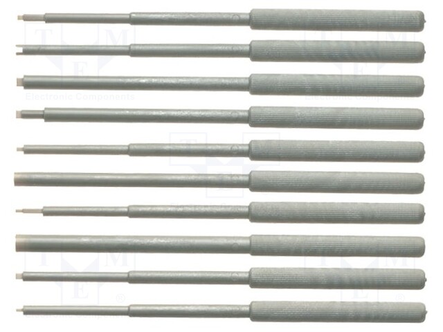
T4857 C.K - Kit: alignment tools | slot; Kit: screwdrivers; blister; 10pcs.; CK-4857 | TME - Electronic components
C.K T4857 | Kit: alignment tools; slot; Kit: screwdrivers; blister; 10pcs. - This product is available in Transfer Multisort Elektronik. Check out our wide range of products.
 www.tme.eu