foo.kamikaze
Active Member
Hi folks, I have an elusive and mysterious protection issue I believe originates from the power supply.
HISTORY
I bought a working Pioneer SX-727 up until I decided to begin rebuilding. I did my research on Audiokarma as I always do before jumping into a rebuild. The first day of the rebuild I turned on the stereo and the relay failed to click. I turned it of and on several times, and thought I better put the rebuild on hold and do some Audiokarma research concerning Pioneer SX-727. I took notes the rest of the weekend, and during the week.
After studying for a week, I pulled out some blank paper and my DMM, and fired up the old Pioneer... CLICK! WTF? I turned it off. I turned it on, click! I did this several times. Click! Click! Click! I paused in silence and thought about it, and decided NOT to troubleshoot the mysterious protection issue.
I began with greasing the 4 outputs... click!
Next, I did the power supply board... click!
I did the tone board... click!
I did the phone board... click!
I did the 1000 uF, 6800 uF, and the other 6800 uF... click!
I did the FM/AM board... click!
I did the protection board... click!
I did the power amp board... ... ... ... ... DOH!
Now what? I bent and wiggled wires. Poked the board with a plastic "poker". Whacked the relay several times... click! I read on Auidokarma that is one sign of a bad relay. I now know what to do. Replace the relay!
Replaced the relay... click!
I replaced the remaining "stray" miscellaneous capacitors about the chassis... click
Shutdown for the day, Saturday, and aimed to put the stereo together Sunday morning.
Sunday morning turned the stereo on... ... ... ... ... No way!
I decided to test the protection board and noticed that PIN 16 was measuring 27.49/36. PIN 16 is connected to power supply PIN 7 by a red wire and PIN 7 was measuring 27.49/36.
The following Saturday I powered the stereo on... click! I grabbed the DMM and was able to set the bias for both channels to 20 mV, and DC offset to 0 mV, and both sets were very stable. I turned the stereo off, and ate lunch. I came back, and turned on the stereo... ... ... ... ... @#$%!!!
I am stumped, exhausted, frustrated, and incredulous.
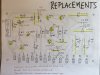
I checked and recorded all the measurements, orientation of components, and noted the replacements in a couple pictures below. I also took an overview pic of the current work I did. The power supply is the "A" variant, AWR-011-A.
Do you see anything wrong?


HISTORY
I bought a working Pioneer SX-727 up until I decided to begin rebuilding. I did my research on Audiokarma as I always do before jumping into a rebuild. The first day of the rebuild I turned on the stereo and the relay failed to click. I turned it of and on several times, and thought I better put the rebuild on hold and do some Audiokarma research concerning Pioneer SX-727. I took notes the rest of the weekend, and during the week.
After studying for a week, I pulled out some blank paper and my DMM, and fired up the old Pioneer... CLICK! WTF? I turned it off. I turned it on, click! I did this several times. Click! Click! Click! I paused in silence and thought about it, and decided NOT to troubleshoot the mysterious protection issue.
I began with greasing the 4 outputs... click!
Next, I did the power supply board... click!
I did the tone board... click!
I did the phone board... click!
I did the 1000 uF, 6800 uF, and the other 6800 uF... click!
I did the FM/AM board... click!
I did the protection board... click!
I did the power amp board... ... ... ... ... DOH!
Now what? I bent and wiggled wires. Poked the board with a plastic "poker". Whacked the relay several times... click! I read on Auidokarma that is one sign of a bad relay. I now know what to do. Replace the relay!
Replaced the relay... click!
I replaced the remaining "stray" miscellaneous capacitors about the chassis... click
Shutdown for the day, Saturday, and aimed to put the stereo together Sunday morning.
Sunday morning turned the stereo on... ... ... ... ... No way!
I decided to test the protection board and noticed that PIN 16 was measuring 27.49/36. PIN 16 is connected to power supply PIN 7 by a red wire and PIN 7 was measuring 27.49/36.
The following Saturday I powered the stereo on... click! I grabbed the DMM and was able to set the bias for both channels to 20 mV, and DC offset to 0 mV, and both sets were very stable. I turned the stereo off, and ate lunch. I came back, and turned on the stereo... ... ... ... ... @#$%!!!
I am stumped, exhausted, frustrated, and incredulous.
I checked and recorded all the measurements, orientation of components, and noted the replacements in a couple pictures below. I also took an overview pic of the current work I did. The power supply is the "A" variant, AWR-011-A.
Do you see anything wrong?