• The move to the new server is done. There are some software and database maintenance updates in process. This has us passing the hat around to help out. We appreciate any donations. Seriously, even a dollar helps. The payment page may be found here - https://www.audiokarma.org/support.html

Pioneer SX-737 rebuild BOM

Thanks Glen. I have DeOxit spray. Are you saying I should spay it into a bottle and then apply it?
Whenever possible yes. The aerosol can doesn't have very good control, and can make a mess when trying to do things such as rotary and slide switches.

As for the re-build, I am still a ways away from that, but I will certainly be taking lots of photos. I have already been studying the service manual and diagrams. I assume I should rely on what is printed on the board rather than the diagram, at least in terms of pin placement.
Do you know how difficult the knobs are to get to for cleaning with DeOxit?

Certainly not the easiest, You access controls from the bottom.

192837-classic_pioneer_sx737_in_extremely_rare_pristine_restored_condition.jpg
 
Looks like the board up front is in the way. Does it have to be moved out of the way to get to the pots?
 
Looks like the board up front is in the way. Does it have to be moved out of the way to get to the pots?

In order to properly access them you need to take the board loose then turn it upward, just as one would if they needed to remove components from the board.
 
Well, I went by Fry's today and they pretty much had everything I needed on my list, and at a better price than Amazon. My receiver arrived as well, so I am working on my DBT.
 
DBT built. I tested it on a radio I have in the garage. I put a 100w bulb in. Radio worked, bulb did not light. So, I hooked it up to my chop saw. Bright light, saw did not turn. Seems like a good test.

Hooked up the receiver to it, Light briefly lite and went out. Receiver stayed on. Turned off and on again, light did not light. I think maybe 100w is too much. I was concerned the bulb went out so I hooked it up to the toaster and it light brightly.

Plugged the receiver into the wall. Powered up fine. Now I need to get the speakers hooked up.
 
Alright, hooked it up to my DM602s and its AWESOME! I didn't push it hard. All the functions work. FM light is out. Light is dim on left side of the dial. The right channel has some static.

Next step is to clean the pots.
 
Update: Right channel was fine. My woofer is messed up. That will be a topic for another board. I swapped it out with my other pair of 602s and it was clear.
I played some music off my phone on the AUX input and let it warm up. All of a sudden, WHAM and no sound. I powered down then back up. Loud popping in the left channel.

Took the phone off and turned the volume all the way down. Powered up, still popping.
 
DBT built. I tested it on a radio I have in the garage. I put a 100w bulb in. Radio worked, bulb did not light. So, I hooked it up to my chop saw. Bright light, saw did not turn. Seems like a good test.

Hooked up the receiver to it, Light briefly lite and went out. Receiver stayed on. Turned off and on again, light did not light. I think maybe 100w is too much. I was concerned the bulb went out so I hooked it up to the toaster and it light brightly.

Plugged the receiver into the wall. Powered up fine. Now I need to get the speakers hooked up.

The 100 watt bulb is fine. Under normal conditions the bulb may illuminate a bit just briefly due to the surge current, until the main power supply caps charge up.
 
Update: Right channel was fine. My woofer is messed up. That will be a topic for another board. I swapped it out with my other pair of 602s and it was clear.
I played some music off my phone on the AUX input and let it warm up. All of a sudden, WHAM and no sound. I powered down then back up. Loud popping in the left channel.

Took the phone off and turned the volume all the way down. Powered up, still popping.

Need to isolate what section of the receiver is actually generating the noise. On some units you can simply pull the pre/out to main/ in jumpers on the back.
But your unit doesn't have those jacks, so the pre amp and main amp would need to be separated internally. If the unit is still doing the same thing after they are separated, then you know the noise is being generated in the main amp section. Just for testing purposes, it would be wise to round up a set of speakers that are expendable in case something goes wrong. You wouldn't want to screw up a good set of speakers testing an amp which might have issues.
 
Last edited:
Since I am probably going to go through a systematic rebuild, does this matter? i am worried about all the problem parts that I have been reading about anyway so need to replace them, but since I will be in there, might as well replace all the transistors and caps right?
 
Since I am probably going to go through a systematic rebuild, does this matter? i am worried about all the problem parts that I have been reading about anyway so need to replace them, but since I will be in there, might as well replace all the transistors and caps right?

If you're going to rebuild you wouldn't need to spend a bunch of time tracing the fault down the components responsible. But it wouldn't be a bad idea to at least
know which "section" of the receiver is causing the issue. Desoldering connecting pins 7 and 15 on the main amp board will separate both channels. Don't unwrap the
wire from the pins, just desolder the whole pin with the wire connected from the board. BTW once you're ready to actually rebuild the board, if you wish you can go ahead and desolder all of the posts so that you can fully separate the board from the receiver. Makes it a lot nicer to work with on the bench that way. Plus it will help keep the wire from being flexed back and fourth to the point where they end up getting broken from their posts. It is solid core wire so its easier to break.
 
Last edited:
Glen, I want to say thanks for all your help so far and also to the other members who have chimed in.

I don't quite understand the test described above both logically and mechanically. If I separate the pre from the main, do I power up with speakers and see if the popping is still there? I assume there would be no input, just amplification. I would need to let it warm up too. Is this correct?

On the pins, if I de-solder from underneath? Will the wire stay intact with the pin?

Lastly, as I put my parts list together, I thought about skipping the mic and the tuner. Should I just replace the two tuner transistors though? If I do that will it need to be aligned?
 
Glen, I want to say thanks for all your help so far and also to the other members who have chimed in.

I don't quite understand the test described above both logically and mechanically. If I separate the pre from the main, do I power up with speakers and see if the popping is still there? I assume there would be no input, just amplification. I would need to let it warm up too. Is this correct?

Ok first the logic, The noise you speak of can potentially be a result of an issue in "both" the preamp and power amp section of the receiver. However much of the time
it's usually one or the other. If you separate the preamp from the amp section and it's still popping over the speakers the way it was, then you know the the noise is being
generated by the power amp section itself. Why? because the preamp is no longer connected to the power amp, and therefore cannot feed any noise into it, which would in turn come over the speakers. Separating the two sections is simply just using the process of elimination, to narrow down the area where the problem really exists.

Next the mechanics,
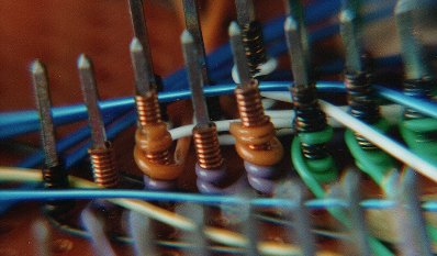
To start with, the non soldered connections are made to the posts with an old but reliable method called wire wrap.
https://en.wikipedia.org/wiki/Wire_wrap
WWexample2.jpg

This method has proven to make reliable connections. However you don't dare unwrap and try to re-wrap it using the same stripped
portion of wire. You won't get a good connection. Also the wire isn't long enough to strip it back to do the connection over. Plus it takes
a special tool to do it right anyway. So then the question becomes, how does one remove a board without messing up the wire wrap?
Well the posts which the wires are wrapped to are just soldered to the PC board. Instead of unwrapping the connections simply un-solder the pin itself
from the board with the wire still attached to it, then you can solder it back when its time to reconnect it.

On the pins, if I de-solder from underneath? Will the wire stay intact with the pin?

Yes, The wire is wrapped tightly, and should be fine provided you don't attempt to unwrap the post.

Lastly, as I put my parts list together, I thought about skipping the mic and the tuner. Should I just replace the two tuner transistors though? If I do that will it need to be aligned?
Unless there is an issue with the tuner relating to them, best to just leave them alone.

 
OK, I am getting my BOM ready for an order. It would be awesome if I could get this up and running by Christmas, but not sure time will permit. I still need to get my soldering skills in check. Seems I donated most of my old electronics that I don't use (VCRs, etc) so I need to find a practice vehicle.

There is one part from Mark's list that is obsolete: http://www.mouser.com/Search/Produc...334virtualkey59850000virtualkey598-DSF050J334
They have this one that is 10% vs 5%: http://www.mouser.com/ProductDetail/Nichicon/UKL1HR33KDDANA/?qs=AU7cqTtHTl7AXFUiok7TRQ==
Not sure this would be good or not. Can someone please help me find a suitable alternative. I am not sure what specs are most important. Mouser does not seem to have anything exact.

I also see the protection circuit relay is on the list. This one scares me a bit as I have read that replacements don't fit into the location. Also, to these solder to wires or to the board?

Lastly, should I replace the filter caps? I did not see them on the list.
 
BACK to the original question: the sx-737 parts list. I just grabbed the text block of parts numbers from my 2013 list post and ran them into mouser's parts list importer, and it only choked on the stacked film caps (dsf). got no time to unchoke that and others can help, so I'll leave you with two links:

The list of lists:http://www.audiokarma.org/forums/index.php?threads/pioneer-recap-lists-sticky-suggestion.457663/

The sx-737 list in the list of lists: http://www.audiokarma.org/forums/index.php?threads/deciding-what-caps-to-use.494440/

Mark, at the bottom of the list you say EDIT 1/2/2015 CHANGED trimpots to types 3386F and 3296Y.
I noticed that there are still two 3386Fs in the parts list. Where those meant to be changed to 3296Y?
 
OK, I am getting my BOM ready for an order. It would be awesome if I could get this up and running by Christmas, but not sure time will permit.
That's not going to be enough time. Not trying to dump a load of pessimism on you, but need to be realistic.
If you are wanting to use the receiver as a gift, best to shoot for some future occasion.

I still need to get my soldering skills in check. Seems I donated most of my old electronics that I don't use (VCRs, etc) so I need to find a practice vehicle.
I could stand to get rid of a couple old PC boards I have stashed away, could send you a couple. Just would need to PM your info to me.

There is one part from Mark's list that is obsolete: http://www.mouser.com/Search/Produc...334virtualkey59850000virtualkey598-DSF050J334
They have this one that is 10% vs 5%: http://www.mouser.com/ProductDetail/Nichicon/UKL1HR33KDDANA/?qs=AU7cqTtHTl7AXFUiok7TRQ==
Not sure this would be good or not. Can someone please help me find a suitable alternative. I am not sure what specs are most important. Mouser does not seem to have anything exact.

You can use this one.
http://www.mouser.com/ProductDetail/Panasonic/ECQ-V1H334JL/?qs=sGAEpiMZZMv1cc3ydrPrF%2bfZ13WJ/r1/qiRpdSGFZEA=

I also see the protection circuit relay is on the list. This one scares me a bit as I have read that replacements don't fit into the location. Also, to these solder to wires or to the board?
The relay doesn't mount on a PC board, it's wired in circuit. Look at the pic I posted of the bottom earlier. You'll see the relay mounts on the bottom, sticking up through a hole in the chassis.

Lastly, should I replace the filter caps? I did not see them on the list.
Yes, what's the diameter in millimeters and length.
 
Last edited:
Mark, at the bottom of the list you say EDIT 1/2/2015 CHANGED trimpots to types 3386F and 3296Y.
I noticed that there are still two 3386Fs in the parts list. Where those meant to be changed to 3296Y?

No, you would get two of each. The Y suffix is a 10k multi-turn pot which would replace the old single turn DC offset controls. The F suffix is a single turn version to replace the old bias control pots. They are not an exact drop in replacement but we'll get to that later.
 
That's not going to be enough time. Not trying to dump a load of pessimism on you, but need to be realistic.
If you are wanting to use the receiver as a gift, best to shoot for some future occasion.
Yes, I think I am being optimistic.

The relay doesn't mount on a PC board, it's wired in circuit. Look at the pic I posted of the bottom earlier. You'll see the relay mounts on the bottom, sticking up through a hole in the chassis.
I see now. Looks like four wires.

I could stand to get rid of a couple old PC boards I have stashed away, could send you a couple. Just would need to PM your info to me.
Thanks so much for the offer. I will find something around here to take apart and trash.

Yes, what's the diameter in millimeters and length.
Not sure yet on the size of the filter caps. I thought I read somewhere here about replacement part numbers. I did not see them in the list Mark sent.

As I continue to read and research, I am thinking of picking up a Hakko FX888D for the job. I am worried I won't have enough experience to dial in the WLC-100. Not sure what the optimal temp should be. Seems like the Hakko would take away that part of the curve a bit.
 
Back
Top Bottom