• The move to the new server is done. There are some software and database maintenance updates in process. This has us passing the hat around to help out. We appreciate any donations. Seriously, even a dollar helps. The payment page may be found here - https://www.audiokarma.org/support.html

Pioneer SX-770 amplifier board diagnosis

19Brendan80

AK Subscriber
Subscriber
Hello all, I have a sx-770 with distorted audio on one channel. I have limited knowledge, but am willing to learn. I have traced it down with an audio probe to the amplifier board. I have marked up the schematic as follows:

Good audio in both channels in Green.
Bad distorted audio in the bad channel in Red.
No audio (that i can tell?) in the good channel at the same point in Blue.
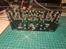
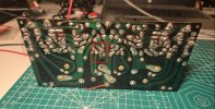
I have also added pictures of where i think the problem is on the top side and marked the solder trace on the back of the board where there is distorted audio.
Does anyone have any ideas of what i should be looking for? a bad capacitor or is it the transistor that is bad? I guess i could recap and replace all the transistors, but i'd rather not just shot gun parts at it. The other repairs on the board were done about 25 years ago by a qualified tech.
Any help would be greatly appreciated. Thanks in advance.

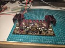
sx-770 amplifier board markup.JPGamp board area.JPG20251123_121641.jpg
 
Register to hide this ad
That's the B+
The feedback could be what's giving that distortion?
One thing I do know for sure, is using jumpers and work on the amp board, on the bench like I see your doing.
The board does not have internal connecting ground/return traces. You have to connect every E pin to its respective chassis location. The scat "E" (Earth) connection is deceiving.
If not you will get weird operation and strange readings.
That TO-220 output is an okay mod but it should be matched.
Check the emitters for value and probably check all the resistors. It won't take long. Looks like there may of been and incomplete repair going on?
Its very easy to mis solder connections on the back of the board.
Use the list of replacement caps and transistors to rebuild the amp. It will reward in the end.
I love these 770's.
 
Wondering why they put this on the bottom and not the top like the one in the other channel...

Screenshot (691).jpg
 
That's originally Q6, 2sc904, but looks like a newer TO-126-3 mounted incorrectly on the bottom of the board for some reason.

Rebuild the amp board with new caps and transistors.
Q1, Q2 KSC1845's
Q3, Q4 KSC2383's
Q5, Q6 KSC2690's
Q7, Q8 KSA1220's
 
That's originally Q6, 2sc904, but looks like a newer TO-126-3 mounted incorrectly on the bottom of the board for some reason.

Rebuild the amp board with new caps and transistors.
Q1, Q2 KSC1845's
Q3, Q4 KSC2383's
Q5, Q6 KSC2690's
Q7, Q8 KSA1220's
You're correct, it is Q6 the 2sc904. I think i will take your advice and buy a kit to do the whole amplifier off of ebay. i will do each board and test afterward with a dim bulb tester. I will also get 4 new matched output transistors to correct the work that was previously done by the tech, even though it worked. (the seller that has the rebuild kits also has theTIP41C transistors, which i assume are already matched?) I did see 2sc91 transistors on ebay, and could replace just the one transistor but it wouldn't be "matched" to the others. My first priority is to get the amplifier board working. I also assume i will need to bias the amplifier after installing all the new parts... I'll have to figure out how to do that. Hopefully the kit will have instructions for that. This is my first attempt at solid state repair... i've done a bunch of tube amplifiers so i do have a basic concept of what's going on. I do know about the base emitter and collector orientation as well so I think i can accomplish this. I appreciate all the advice, thanks!
 
Yes, your thinking tubes.
No real need to match the outputs on this particular cap coupled amp circuit.
The guys will tell you to swap out the trimmers for better modern ones. They do have a bad reputation.
The components will not kill the budget on this receiver.
You could save some money and order the components from Mouser or DigiKey but it takes time to build the list. There are a few threads that have complete lists. Maybe the guys will help with that?
The list I posted above is old and two of the equivalents are obsolete.
Link the kit you're looking at.
 
You're correct, it is Q6 the 2sc904. I think i will take your advice and buy a kit to do the whole amplifier off of ebay. i will do each board and test afterward with a dim bulb tester. I will also get 4 new matched output transistors to correct the work that was previously done by the tech, even though it worked. (the seller that has the rebuild kits also has theTIP41C transistors, which i assume are already matched?) I did see 2sc91 transistors on ebay, and could replace just the one transistor but it wouldn't be "matched" to the others. My first priority is to get the amplifier board working. I also assume i will need to bias the amplifier after installing all the new parts... I'll have to figure out how to do that. Hopefully the kit will have instructions for that. This is my first attempt at solid state repair... i've done a bunch of tube amplifiers so i do have a basic concept of what's going on. I do know about the base emitter and collector orientation as well so I think i can accomplish this. I appreciate all the advice, thanks!
Don't buy anything from hifiaudio. They suck.

marblehead kits are questionable.
 
Yes, your thinking tubes.
No real need to match the outputs on this particular cap coupled amp circuit.
The guys will tell you to swap out the trimmers for better modern ones. They do have a bad reputation.
The components will not kill the budget on this receiver.
You could save some money and order the components from Mouser or DigiKey but it takes time to build the list. There are a few threads that have complete lists. Maybe the guys will help with that?
The list I posted above is old and two of the equivalents are obsolete.
Link the kit you're looking at.
Well that's good news on the output transistor. I'll just get the one original style. Here's the link for the kit: https://ebay.us/m/fJTodu
 
Back
Top Bottom