petehall347
the brandy coffee man
i would test them in circuit first and if they read out of spec lift one end and test again .



Right channel is good when left channel Darlington is removed. just for reference.That should the the RIGHT channel. The ±40VDC power supplies appear to be intact. The general suspicion is that the cement 0.22Ω resistors (the white ceramic rectangular ones) have a problem.
Please check the resistances of those resistors and report in with results. I expect the readings to be infinite instead of less than 1 Ω.
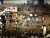
interesting that the brown, black, black, gold, in my photo tests .090, however I have another SX-780 and when I tested it also I came up with same readings. Thought these should read 10.00 ohms , but maybe I'm confused? I was testing resistors other than what probably need testing.

interesting that the brown, black, black, gold, in my photo tests .090, however I have another SX-780 and when I tested it also I came up with same readings. Thought these should read 10.00 ohms , but maybe I'm confused? I was testing resistors other than what probably need testing.
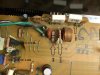
These resistors in location R260 and R259 are actually Brown, Green, Brown, Gold and are both showing 150.86 and 151.30 , so are we on the same page?
I've added a picture of what I've checked. When checking these I've verified both channels resistors, even though my photo only shows one channel.
So what should I test or check Next?
......snip.....
Next step is testing specific small transistors by removing them and performing the 6 way diode test (specific example and sample results in post #11) looking for gross faults.
I checked, you have NOT named the channel that gets sound, and thus I must complicate things by naming components in BOTH channels.
Q11, Q13, Q15 for the left channel, and q12, q14, q16 for the right channel - depending upon which channel is not working.
...snip....