• The move to the new server is done. There are some software and database maintenance updates in process. This has us passing the hat around to help out. We appreciate any donations. Seriously, even a dollar helps. The payment page may be found here - https://www.audiokarma.org/support.html

Pioneer SX-780 Problems Need Help Please

Here are some voltage readings I took yesterday. All voltages are vdc uno.

Q6, E 0.001
Q7, E 0.017
Q8, E 0.012
Q9, E - 40.07
Q10, E - 40.55
Q11, E - 40.24, C VERY UNSTABLE, B - 39.72
Q12, E - 40.07, C - 9.5, B -40.21
Q13, X -41.12, Y -2.062, Z -40.20
Q14, E 0, C - 9.53, B 0
Q15, E 13.49, 13.48, 12.95
Q16, E 13.38, C -6.579, B 12.84
Q19, E 13.42, C 50.85, B 13.97
Q20, E -41.12, C -53.03, B -41.12
Q21, E 15.22, C 14.08, B 14.69
Q22, E -52.53, C -52.53, B 0.001
Q23, X 50.58, Y 14.07, Z 14.04
Q24, X -52.53, Y -53.01, Z -52.24

Work done so far:
Cleaned and lubed all pots and switches
Replaced the PA3004 IC with the new board and components
Replaced the following electrolytic capacitors
- C103, C104, C301, C302, C303, C304, C307, C308, C314, C315, C316, C318, C319
I also replaced the transistors MTF suggested, and Q26. I removed and tested Q19, Q20, and Q25.

I checked the board for cracks (very closely) and found none
I ohm'd every ground point I could find and they are good

I reflowed a bunch of solder joints
Pulled one leg of several resistors and tested them. All within spec.
It is in protection now and no amount of twisting, turning, bumping, etc will bring it out. No sound from headphone jack.
 
Last edited:
original module which channel?
your replacement module, obviously the other channel.

output voltages? Pin 9? pin 6?
get ready to disconnect both modules, put in substitute resistors for troubleshooting.


150 ohms from pin 0 to pin 8
150 ohms from pin 1 to pin 3

expected results from substitute resistors OR working pack.
Left
0: +1.4
9: 40.2 raw dc, can vary
8: 0
3: 0
2:-40.3 raw dc, can vary
1:-1.4

Right
0: +1.4
9: 40.1 raw dc, can vary
8: 0
3: 0
2:-39.9 raw dc, can vary
1:-1.4

(nothing connected to pin 4, 5 or 6 either in the module or outside in the receiver.)
 
original module which channel?
your replacement module, obviously the other channel.

output voltages? Pin 9? pin 6?
get ready to disconnect both modules, put in substitute resistors for troubleshooting.


150 ohms from pin 0 to pin 8
150 ohms from pin 1 to pin 3

expected results from substitute resistors OR working pack.
Left
0: +1.4
9: 40.2 raw dc, can vary
8: 0
3: 0
2:-40.3 raw dc, can vary
1:-1.4

Right
0: +1.4
9: 40.1 raw dc, can vary
8: 0
3: 0
2:-39.9 raw dc, can vary
1:-1.4

(nothing connected to pin 4, 5 or 6 either in the module or outside in the receiver.)
Original module Lch
My replacement module Rch

The output voltage at Pin 9 is very unstable. So much so, I can’t get a reading. With resistors in it is -0.271vdc
Pin 6 is -5.079

Modules disconnected and resistors installed voltages.
Lch
0: -0.037
9: 41.42
8: -0.267
3: -0.267
2: 41.07
1: -0.157

Rch
0: 0.104
9: 41.15
8: 0.001
3: -0.121
2: -41.13
1: -0.351
Nothing connected to pin 456 inside or outside the receiver

Voltage readings before disconnecting and installation of resistors.
Lch
0: 0.929
9: 0.002
8: 0.003
3: very unstable bouncing -0.7xx to -2.4xx
2: 0.002
1: 0.002

Rch
0: -7.192
9: 40.011
8: -5.120
3: -51.134
2: -40.790
1: -9.521

All voltages are vdc

The unit came out of protection and music from both channels of headphones with the resistors installed.

I shut it down, waiting on further instructions.
 
Last edited:
I don't like those pins 3 & 8 on the right channel module with the substitute resistors.
there is SUPPOSED TO BE only 0.44 ohms between them.
I think R264 or R266 is open circuit.

I'm also quite suspicious of the left module, maybe BOTH.

get the 0.22 Ω resistors fixed, and try again.

music in headphones with resistors substituting for modules is pretty damning for the modules.

3 stages to a power amp:
1 differential input stage
2. voltage amplifier stage
3. current drive stage.

the modules are purely stage three, current drive... voltage amplification is done by then. so sound in the headphones is a STRONG indicator.
 
Last edited:
I don't like those pins 3 & 8 on the right channel module with the substitute resistors.
there is SUPPOSED TO BE only 0.44 ohms between them.
I think R264 or R266 is open circuit.

I'm also quite suspicious of the left module, maybe BOTH.

get the 0.22 Ω resistors fixed, and try again.

music in headphones with resistors substituting for modules is pretty damning for the modules.

3 stages to a power amp:
1 differential input stage
2. voltage amplifier stage
3. current drive stage.

the modules are purely stage three, current drive... voltage amplification is done by then. so sound in the headphones is a STRONG indicator.
Mark, I only had three 0.2 ohm resistors in my stock. They are unused (new.) I did an ohm check on them (Fluke 117 DMM) and they all read 0.3 ohms. The old resistors on the Lch read 0.4 0hms, and 1 on the Rch read 0.3 ohms and the other one read 0.4 ohms. I put two of the new resistors on the Rch, and 1 on the left along with the old one that read 0.3 ohms.
New readings:
Lch
0: -0.073
9: 40.90
8: -0.293
3: -0.293
2: 40.95
1: -0.539
Rch
0: 0.096
9: 40.90
8: -0.124
3: -0.123
2: -40.90
1: -0.350
All vdc
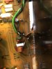
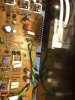
I looked through my post and thought I had mentioned it but apparently I didn’t. At Lch there is a 4.7 microfarad cap, a 130 ohm resistor, a zener diode, and an ear wig cap wired in with pin 11, and same thing at pin 3 (Rch.) I will include a photo. Sorry I missed this. It was apparently done by someone else in the past.

Since I didn’t have the correct resistors for R263, R264, R265, and R266, I am going to order them. I only used the others for this test.
 

Attachments

  • image.jpg
    image.jpg
    100.4 KB · Views: 20
  • image.jpg
    image.jpg
    130.4 KB · Views: 22
Last edited:
Well, I suppose I did or said something wrong. I had three new .2, 1W resistors. They are not .22 resistors. I know that. They measured .3 on my Fluke and Klein DMM’s even though they are new. I thought (apparently wrong) that they would suffice for the test. I am getting the correct resistors which was always my intention. Silence is deafening. My crystal ball is broken. I cannot determine for sure if I need to just shitcan the STK’s and order new boards and components. I guess that’s what I will do.
 
Set your meter to ohms, short the leads together and measure the resistance in the probes/cables. when you measure the resistors the probe/cable resistance needs to be subtracted from the total. Bets are they will actually be close to .2Ω
 
Set your meter to ohms, short the leads together and measure the resistance in the probes/cables. when you measure the resistors the probe/cable resistance needs to be subtracted from the total. Bets are they will actually be close to .2Ω
Thanks Larry, I actually knew that but lose sight sometimes. Thanks again for the reminder. I have a Fluke 117 and Klein MM720. Both are auto ranging DMM’s and shorting the leads is 0.1 ohm.
 
I don't like those pins 3 & 8 on the right channel module with the substitute resistors.
there is SUPPOSED TO BE only 0.44 ohms between them.
I think R264 or R266 is open circuit.

I'm also quite suspicious of the left module, maybe BOTH.

get the 0.22 Ω resistors fixed, and try again.

music in headphones with resistors substituting for modules is pretty damning for the modules.

3 stages to a power amp:
1 differential input stage
2. voltage amplifier stage
3. current drive stage.

the modules are purely stage three, current drive... voltage amplification is done by then. so sound in the headphones is a STRONG indicator.

Are you telling me that the modules are bad or going bad? Do I need to replace them?

Help please!
 
Last edited:
In my search for the .22ΩK (10% tol) resistors I found two that should work.

YAGEO PNP3WVJT-73-0R22
VISHAY AC03000002207JAC00
Comments?
 
Last edited:
Yageo is non stocked @ mouser. Vishay is. Same with Digikey.

Vishay should be ok. I'd mount them vertically with heatshrink tubing or spaghetti tubing on the top lead back to the hole.
 
when I managed to steal time to investigate last Sunday's post I found myself trying to figure out the stuff in the pictures.

not angry, just severely distracted. Have you looked at my postings and intervals last week. A post is rarely just a 30 second drive by.

see... Larry's gotcha too...


Small emitter resistor variations aren't going to hurt things -

Rch
0: -7.192
9: 40.011
8: -5.120 <<<<<<<<<<<<<<<<<<<<<<<<
3: -51.134 <<<<<<<<<<<<<<<<<<<<<<<<
2: -40.790
1: -9.521

but supposedly 1 ohm or less of resistance has 5 volts on one side and 51 volts on the other.
that just ain't gonna fly....

This module stuff:
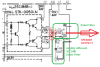
The module has SIX pins:
pin 9 is plus power rail
pin 2 is minus power rail

pins 0 & 1 are supposed to be the drives for the npn (1.4v) and pnp (-1.4v) halves of the push pull module.

pins 8 & 3 are the audio "outputs" being fed into two 0.22 ohm resistors, and the common point between the two resistances is the OUTPUT. Connect that to the two zobel filters, and after the filters , well it's the protect circuit relay, speaker select switches and finally the speakers.
The idle current is read across those two resistors, pin 8 (+) to pin 3(-). Whatever millivolts across them for whatever mA idle current through the 0.44 ohms.

That's it, all six.

upload_2023-3-31_23-51-13.png

Now when tying the extra 150 ohm resistors to 0 to 8, and 1 to 3, you are is SIMULATING the module
It won't drive current, but it WILL be able to have it's DC offset set - which is a LARGE part of verifying
that the rest of the circuit is behaving itself... Q11, Q13, Q15, Q7, Q9, Q5.
Very high impedance headphones (non-loading) will register sound of approximately correct amplitude..


upload_2023-4-1_0-8-52.png

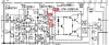
Rosetta stone for this amp:
Q7 is the differential amp input stage
Q9 one side is diode wired, a part of the other side's current "mirror" to load Q7 as a diff amp.
Q11 & Q13 is the (darlington) voltage amplifier stage which also has the idle current splitter (inside the module)
Q11 & Q13 are run by current from Q15 which is a fixed current source. same current no matter if no audio.
Current is the voltage across the 100 (R261) Ω resistor divided by it's resistance.
On this schematic, it's (39.5v - 39.2v ) 0.3v / 100 Ω = 0.003 A or 3 milliamps.
Finally
There's Q5 for dc offset adjust. Rule of thumb: base is 0v, emitter s/b ~ -0.6 to -0.7V (Vbe) collector is gonna be the + rail (+40v).
Take it on faith - it's a base stealer configuration, starts out at 36k Ω (R237) and has 150kΩ of latitude as well as an additional 100kΩ of resistance to summon forth. It wants to have the same base voltage as Q7, and the collector current is adjusted so that with the gain ( base current) being similar to Q7 the transistor is operating in approxamently the same condition as half of Q7. Obviously as the resistance increases, the collector current decreases, accommodating higher gain transistors.
Then as things heat and cool it sucks up or spits out the difference in base voltage / current.
That's why Q7 pair is matched, and Q5 is as close as possible to Q7's specs.
Q15 & Q13 have about 40v collector to emitter while 3mA is flowing, that generates 0.120w of heat each. warm but not hot.

with the above, a great many people should be able to reason their way through the non-module sections of the SX-780.
 
Last edited:
when I managed to steal time to investigate last Sunday's post I found myself trying to figure out the stuff in the pictures. I apparently missed it but did you figure out what the components were in the pictures. I kick myself for missing that I failed to post that they were installed in the receiver. I understand you are busy and I thank you for taking time to help me. It is appreciated more than words can describe.

not angry, just severely distracted. Have you looked at my postings and intervals last week. A post is rarely just a 30 second drive by. Yes, I have seen your postings and understand that you are not just helping me but many others. I thank you for that!

see... Larry's gotcha too... I have to admit that I am lost on this.


Small emitter resistor variations aren't going to hurt things -


but supposedly 1 ohm or less of resistance has 5 volts on one side and 51 volts on the other.
that just ain't gonna fly....

This module stuff:
The module has SIX pins:
pin 9 is plus power rail
pin 2 is minus power rail

pins 0 & 1 are supposed to be the drives for the npn (1.4v) and pnp (-1.4v) halves of the push pull module.

pins 8 & 3 are the audio "outputs" being fed into two 0.22 ohm resistors, and the common point between the two resistances is the OUTPUT. Connect that to the two zobel filters, and after the filters , well it's the protect circuit relay, speaker select switches and finally the speakers.
The idle current is read across those two resistors, pin 8 (+) to pin 3(-). Whatever millivolts across them for whatever mA idle current through the 0.44 ohms.

That's it, all six.

View attachment 2845954

Now when tying the extra 150 ohm resistors to 0 to 8, and 1 to 3, you are is SIMULATING the module
It won't drive current, but it WILL be able to have it's DC offset set - which is a LARGE part of verifying
that the rest of the circuit is behaving itself... Q11, Q13, Q15, Q7, Q9, Q5.
Very high impedance headphones (non-loading) will register sound of approximately correct amplitude..


View attachment 2845965

Rosetta stone for this amp:
Q7 is the differential amp input stage
Q9 one side is diode wired, a part of the other side's current "mirror" to load Q7 as a diff amp.
Q11 & Q13 is the (darlington) voltage amplifier stage which also has the idle current splitter (inside the module)
Q11 & Q13 are run by current from Q15 which is a fixed current source. same current no matter if no audio.
Current is the voltage across the 100 (R261) Ω resistor divided by it's resistance.
On this schematic, it's (39.5v - 39.2v ) 0.3v / 100 Ω = 0.003 A or 3 milliamps.
Finally
There's Q5 for dc offset adjust. Rule of thumb: base is 0v, emitter s/b ~ -0.6 to -0.7V (Vbe) collector is gonna be the + rail (+40v).
Take it on faith - it's a base stealer configuration, starts out at 36k Ω (R237) and has 150kΩ of latitude as well as an additional 100kΩ of resistance to summon forth. It wants to have the same base voltage as Q7, and the collector current is adjusted so that with the gain ( base current) being similar to Q7 the transistor is operating in approxamently the same condition as half of Q7. Obviously as the resistance increases, the collector current decreases, accommodating higher gain transistors.
Then as things heat and cool it sucks up or spits out the difference in base voltage / current.
That's why Q7 pair is matched, and Q5 is as close as possible to Q7's specs.
Q15 & Q13 have about 40v collector to emitter while 3mA is flowing, that generates 0.120w of heat each. warm but not hot.

with the above, a great many people should be able to reason their way through the non-module sections of the SX-780.
Thank you Mark for the response and explanation. A death in the family is going to take me away from the (attempted) repair for a week. I will resume the work when I return on Friday.
 
Larry's gotcha reference to shorting probes 1st to get probe capacitance.
 
well, when I had gone back and re-read this entire thread, I came upon this gem:

All voltages are vdc

The unit came out of protection and music from both channels of headphones with the resistors installed.

I shut it down, waiting on further instructions.

You had installed the resistors in place of the modules, and music in the headphones says things are pretty healthy.

when the output's dc voltage offset can be controlled - that's the icing on the cake.

If it didn't work before that , we have now proven it's not likely the 780's fault...

blame the module.

After I extracted the designed current of 0.003A or 3 mA from the Q15 current source documented in the schematic
I now have doubts of the resistance value, we used 2 x 150 = 300 ohms x 0.003mA = 0.9v = +0.45 and -0.45
we want 2.4 (+1.2 , -1.2) volts with 3 mA, thus 2 x 400 = 800 ohms...

The + and - split of pins 0 and 1 is decided by the DC offset adjustment.
the average of the pins 3 and 8 - done by the 0.22 ohm resistors.
Thus get the dc offset to 0.000v and pins 0 & 1 should be symmetric.
 
Last edited:
I apologize for the silence. My wife and I had to go out of state for a death in the family and apparently caught a bug or Covid during the trip. I haven’t felt like doing much lately but will get back on the 780 repairs when I do. Thanks for all the help and support.
 
Update on this SX-780. I have had a few health problems and was not able to work on any equipment for awhile. Hopefully those are all behind me and I can get on with some of the work I need to complete...for myself. The 780 owner decided he didn't want to proceed with it any further at this time. So it is packed up and on the shelf awaiting his decision to continue, or pick it up as is. So, with that out of the way I was able to get my McIntosh MAC-4100 back on the bench yesterday and by the end of the day it was singing again.

I want to thank MTF, larryderouin, and everyone else who helped me with this unit. Mark, you are definitely a treasure and when and If I do take this unit on again, I know I will have your knowledge from this thread to do so.
 
Back
Top Bottom