• The move to the new server is done. There are some software and database maintenance updates in process. This has us passing the hat around to help out. We appreciate any donations. Seriously, even a dollar helps. The payment page may be found here - https://www.audiokarma.org/support.html

Pioneer SX-950 Power Up

tinkerer

AK Subscriber
Subscriber
Hello and Season Greetings. In the process of cleaning up someone's mess on a SX-950. 3 TO3 outputs found in a bag inside unit, all 3 test bad. Amp board and heatsink loose and flopping around. Resistors R51 & R55 missing and assumed fried. Resistors R37, R39, R67 also fried. All these components are associated with the left channel. I would like to replace the missing and fried components, along with the 2SA726s transistors and test voltages from the Power Board (AWR-101) and the Amp Board (AWH-050). Can I remove the remaining TO3 outputs, both the left and right channel, and power the unit up to test voltages?
 
Register to hide this ad
I think the best place to start is checking all the components on the amp board. Replacing the idle and bias trim pots with more reliable Bourns pots is a good start. Check the compensating diodes for condition (The ones mounted to the heatsink). Lift each component from the board (desoldering one leg) and checking. Transistors are best checked off the board. Better yet replace them using the recap lists here on AK. You got this unit in a heap. You almost need to start from scratch. There are great past threads on this 950. A very nice machine when complete.

I am not sure if you can check voltages without the output drivers installed. Another AK’er may shed some light on this.
 
Thanks for the input. I think you are right it's pretty much start from scratch. I've ordered new outputs and don't want to smoke em right off. I do have a dim bulb tester for power on. I have replaced the 2SC1318's Q3, Q5, and Q7 on the power board, but they all tested good out of circuit. So I guess I'll pull some transistors on the amp board to see if i can find a culprit.
 
The compensating diode is real delicate and the leads like to break at the base of the diode so take care when moving the board around while working on it. If you check all the components and replace the bad parts including the pots, you should be in good shape. I found out you don’t really need the 5.1 ohm shorting plugs for the trim adjustments, just turn the volume down to its stop. 100 watt bulb in your DBT. The pots when shipped are at their middle adjustment, good for the first start. If you don’t replace the pots you better check for operation, if they have an open spot your back to step one (Good by new drivers)! Clean them with Deoxit and let them sit for a day then check’em again.

One other thing; the power supply board runs hot and is known for running on the ragged edge. It may need some work as well, Hope that its good enough to get the set up and running.
 
Last edited:
Yep I am aware of the delicate diodes, thanks for the reminder. Are the Pots on the SX-950 a known issue or just vintage Pots in general?
 
vintage pots in critical locations. that circuit going open circuit is bad news. corrosion on the moving tap's slider's contact's length is almost impossible to deoxit.

an offset pot going open circuit would be annoying as long as the protect circuit is working correctly. idle circuit going open circuit for just an instant can instantly destroy the drivers, outputs, emitter resistors (BOTH driver and output stages), wiring, traces etc... one heck of a current pulse.

the sx-950 amplifier will DC balance with the outputs disconnected.

CHECK your driver transistors and their 150 ohm emitter resistors AS WELL AS their collector diodes. before adding power.

usually I don't tune for smoke, by the time I apply power, it's no longer an unknown unit in an unknown state. At that point I expect it to work.


(btw what ever happened with that tuner?)
 
Last edited:
Sounds like new pots are a good investment and preventive measure. And to be clear I won't destroy anything by powering up without the outputs?
 
Sounds like new pots are a good investment and preventive measure. And to be clear I won't destroy anything by powering up without the outputs?

1. yup

2. nope, as long as the bare sockets are insulated (and double check the resistor from the center of the 150 ohm resistors to the feedback terminals; 5.1k??)

remember that even without the outputs, too much "idle current" will fry the drivers because THEIR current is also controlled by that voltage across the stv diodes and the trimpot.
 
Thanks Mark. I understand everything except you lost me on the feedback measurement. I see the 5.6k resistor between the 150 ohm resistors on the schematic, and on the board, but am not sure where the measurement is to be taken and what I am measuring.
And secondly I was unable to get any work done on the unit today, and the next few days are looking pretty busy also. So I have some catching up to do just to get to the checking voltages part. At any rate I will post my progress as soon as I can.
 
no measure, just continuity to provide some DC feedback to stabilize the amp.

take your time - just because I was able to answer quickly a few rare times doesn't mean we are rushing you. If the delay becomes more than several weeks, then some might think the thread has been abandoned.
 
Update: Had some time today and here is wht I've done thus far.
1) Replaced the .5 ohm 5 watt resistors at R51, R53, R55, R57, two of these were missing and the other two tested bad. Also replaced R58 on the other channel which had been replaced with a .56 ohm resistor by someone.

2)Replaced the 150 ohm resistors at R37, R39, these were toast.

3)Replaced the 100 ohm resistor at R67 also toast.

4)Replaced VR3 and VR4 100 ohm trimpot. VR3 was frozen (welded?) and would not turn at all, must have been hit by a lot of voltage. Decided to check the other channel and the resistance reading on VR4 was all over the place, could not get a steady rise or decline in resistance during adjustment, so I replaced it also. I happen to have a QX-949 donar board that had good steady pots, so I used those. I would liked to have ordered new ones but I'm on a deadline and a budget, so I think these will work. The 10K trimpots checked out good.

5)Replaced diode D7, D8 1S1885 with 1N4004. Both diodes tested bad and one is L and one is R Channel, which now makes me wonder about the right channel which I thought was in pretty good shape.

6) Replaced the 2SA726s transistors on both L and R Channels with KSA992FBU, 4 total which all tested good.

Good call on the trimpots, I don't typically pay much attention to them for some reason. I guess I consider them more mechanical than electrical, and if they go back n forth I figure they r working.

Will do more testing on the amp board tomorrow, also want to go back to the power supply and check the diodes.

PS to Mark: The tuner went back in the box, back in the heap, and may stay there forever. (Waiting for you to come up with some clever fix !! :))
 
Last edited:
More testing more issues.

I had missed diodes D8, D10 on the amp board in my initial pass, and found D8 to be bad and replaced it with 1N4004. D10 tested good but was replaced with same 1N4004.

Tested 2SC1628 @ Q7, Q8, both tested good but replaced with KSC3503DSTU.
Tested 2SA818 @Q5, Q6, both tested good but replaced with KSA1381ES.
Tested 2SD381 @Q9, Q10, Q9 tested bad and both replaced with KSC2073TU.
Tested 2SB536 @Q11, Q12, both tested good but replaced with KSA940TU.

Noticed a dark area on the amp board (AWH-050)and under futher inspection found the trace from Pin 14 to diode D7 burnt. Checked the other side and the trace from Pin 29 to diode D8 was also burnt. These both relate to Pin 18 on the Power Supply Board (AWR-101). This is turning into a major headache. I have repaired traces before and they are always a pain. This one is an S shape from Pin to Pin. If anyone has any simple ways of repairing traces I like to hear them. Sometimes I scrap down to the copper and solder a cut off lead from a component, and just patch across the bad zone, and sometimes I connect a copper wire Pin to Pin if it's not a real crooked path and not a long disance. Any suggestions would be appreciated. The bigger question is: What caused all this destruction? There is a lot of carnage.

Tested the Diodes (in circuit) on the Power Supply Board and they seem OK. Should I test them out of circuit?
 
I like to use cut resistor or cap wire and jump to the next component on that trace. It's a little butchery, not to bad. I'll shape the lead to conform to the original trace.
 
Last edited:
Yep, probably the best way to be sure of a good connection. This one is probably 2-1/2" long to connect the 2 closest components. I usually try to desolder the connections and do a u turn around with the jumper and resolder.

Looking at my list of dead and fried components any idea what caused all this?

Thanks Zeb for the reply:)
 
:rolleyes:Use some 22 gauge solid core to route between.
Something happened on the 106 board in the area were you and Mark are headed. I am interested to find out, but I do know one thing. If it was me, it was something I did. :yes:

Don't give up!
 
Last edited:
Got the burned traces repaired, and have continuity to all the right places.
Gonna recap the amp board but need to place order, so gonna take a few more days before I even think about applying power.

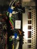
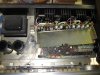
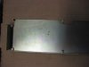
Here is the history of the receiver as best I can discover. It is a one owner. About 15 years ago he was having an issue of some sort and took it to a tech for repair. Either the tech didn't know how to fix it or didn't want to, but evidently tried a patch job, and then gave up and left it half unassemled. It is unknown what problems still existed at that point. Pic 1 is what I found when I opened it up. After 15 years the owner drags it out of his closet, and not remember what state the unit was in, plugs it in and turns on the power. I think the amp board metal holder, which was laying loose in front of the amp board, shorted across the heatsinks at Q9 (2SD381) Q11 (2SB536) and Q10 (2sd381) as evidenced by pic 2. What was already blown and what got blown is hard to know. Pic 3 is the tech's solution for the 2 missing .5 ohm resisters, and the reason the metal amp holder would not go back on in it's proper location. At any rate I have a few more resistors to check and the recap. At that point I am considering applying power even though it scares the heck out of me.
 

Attachments

  • IMG_2965.JPG
    IMG_2965.JPG
    124.6 KB · Views: 60
  • IMG_2992.JPG
    IMG_2992.JPG
    64.4 KB · Views: 45
  • IMG_2987.JPG
    IMG_2987.JPG
    66.9 KB · Views: 61
I know that scared feeling you’re talking about. It wasn’t that long ago I found out about the DBT, what a godsend. I don’t even want to talk about what I did before I built one. Then I bought a variable transformer and a Simpson 390. I tried to use the combo to no avail. Then the DBT, cheap and very effective. It’s the only way to go. It’s all a process. Just know: if you checked all the components, checked for polarity and orientation on the replacement transistors and diodes you’re really close. The DBT will stand a good chance of catching any missed issue. The other side of the scared is the feeling when the set fires up, adjusts to specs, and plays your favorite sounds. Brings tears to my eyes every time. :tears:
 
RE: Dim Bulb Tester
It was my understanding that when using a DBT I should start with a 30 watt bulb and work my way up. Or do I have that reversed?
 
60 to 100 watts, and the DBT will ONLY protect the output transistors, there is still the possibility of smoke...

i tkink i already said on this thread that the amp can be powered up without the output transistors connected - and with that done, I will tell you from voltage readings when it's safe to install them. There are people here that are a great help, having traveled this path before, but they can only go so far before they are winging it, so there are only a few that should vet that choice and be sure it's ok...
 
Got it.
Having checked about everything I know how to check on the Amp Board, keeping in mind that I still have a recap to do, what is your suggestion regarding the Power Supply Board AWR-101?
 
Back
Top Bottom