• The move to the new server is done. There are some software and database maintenance updates in process. This has us passing the hat around to help out. We appreciate any donations. Seriously, even a dollar helps. The payment page may be found here - https://www.audiokarma.org/support.html

Pioneer SX-950 relay not clicking voltages not right. THANKS!! MARK.

daveyh

Super Member
I have a rebuilt the power supply, the protection board and the amp board with all new caps and transistors and checked the diodes mounted to the heat sinks and replaced all adjustment pots with new Bourns according to the AK post available here. I have done this before any times on different units and use the same parts. I have pulled and checked and added new insulators and thermal grease to the outputs. Checked them all to be good before reinstalling them. This time my voltages are not correct, Could it be a bad power transformer?

Here's what I have.

Using a 75 watt bulb on my DBT

-14.23 off main both filter caps.

Gray wire off of the relay 0.167 DC # 9
Black and white off of relay 1,15 DC # 11

DC voltages off of PS

1. 0
2. 3.16
3. 3.16
4. 7.30
5. 7.30
6. 18.11
7. 18.11
8. 1.16
9. 1.16
10. 1.16
11. 0.503
12. 0
13. - 8.10
14 - 9.19
15. -3.13

What's going on?
 
Last edited:
Register to hide this ad
dbt may be strangling the unit. double it's wattage and see what the voltages do.

pins 5 & 13 are direct readings of the zener voltage. yours acts like around 8v or so instead of 14v and 13v.
 
Last edited:
Mark, I changed ZD1 and ZD2 in the PS but still has the problem. Is that the ones you are taking about?
 
not a valid test. especially not from 75 watts to 100 watts with NO power supply readings.

put in the 100 AND the 75 in parallel then read and report the power supply voltages just like in post #1.

You have a power supply problem to rectify before you EVER think about clicks.
Right now the power supply ain't putting out enough voltage to click the damn relay even if it wanted to!!!!

instead of 51.5v, you're getting 18, and for the 36.5v for the relay? LESS THAN TWO!!!! yes I am a bit irked.
 
I had to build a new DBT with two bulbs so I could put the 100 AND the 75 in parallel.

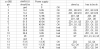
DC voltages off of PS. Here is what I get.

1. 0
2. 5.05
3. 5.05
4. 12.96
5. 12.96
6. 49.04
7. 49.04
8. 5.85
9. 5.85
10. 5.85
11. 4.03
12. 0
13. -13.35
14. -13.35
15. -0.460
 
The mere fact that the bulb glows dimly and that you could take these readings means it "passed the test" and is pointless (and mildly harmful) to STAY on the DBT. Not until you test idle current after working on the amps will you need the DBT for now.

First glance of numbers shows the main regulated voltage is getting better, but the secondary regulators that depend upon it, are not working or not working correctly.

Since you just rebuilt it, check those transistors (Q5 36.5v, Q7 28v phono) for correct installation - ESPECIALLY if the original transistors in those positions are a different case style.

upload_2023-3-21_21-14-52.png
 
Mark.Thanlk you Relay now clicks. With your help I found one of the problems. Q5 in the power supply had one leg backwards. Fixed ix and now here is what I get. DC voltages off of PS.

Still on the dual bulb tester

1. 0
2. 5.07
3. 5.08
4. 12.96
5. 12.98
6. 49.18
7. 49.21
8. 34.96
9. 35.00
10. 35.00
11. 26.85
12. 0
13.-13.37
14.-13.52 -51.15?
15. -4.28 -19?

ZD2 is new and checks to be ok.

Thought I should mention can not set DC offset or Bias. I have installed new pots. 10k ohm and 100 ohm. Do not know if this is related.
 
Last edited:
Was able to get the voltages up. Able to set 0v DC and 20mA bias to correct settings.
14. -51.2
15. -18

Play the FM radio and don't have any power like I am used to. I can turn it up all the way and it's like a 25w receiver. Something is holding it back. I am using the old outputs some check to be 40 hfe. Do you think that could be the problem?? Any ideas???
 
There is a muting circuit on the tuner, Q10 & Q11. You could try pulling them to see if it gets louder. Usually it's malfunction is worse, but.....

Tuner output voltage should be ~.125 volt - a normal line level of 150 millivolts.

Get another receiver and check your pre-outs to see if they are low, feed substitute pre-outs to the 950's power amps...
 
I cut the legs off of Q10 and one side in the FM section was normal sounding good power. The other side did not work at all after cutting the legs.

The amp section is OK. I checked it and sounds fine in aux and phono, Do you still want me to check it through the pre-outs?

Where do I measure the output voltage so I can see what is.
 
No preout checking needed. aux and phono prove it.

Q10 mutes one side of FM, Q11 mutes the other side of FM, Q12 controls Q10 & Q11. MUTE ain't simple.


C57 is a CSSA cap - a shoot on sight sky blue SANYO capsistor.... a 0.1u film cap is fine there.
It's supposed to be a small time delay holding muting on, the cap failure makes the timing infinite.
subs:
2sa733 > ksa992
2sc1312 > ksc1845

upload_2023-3-25_21-4-14.png
 
C57 is a CSSA cap - a shoot on sight sky blue SANYO capsistor.... a 0.1u film cap is fine there.
It's supposed to be a small time delay holding muting on, the cap failure makes the timing infinite.
subs:
2sa733 > ksa992
2sc1312 > ksc1845

Mark. I changed the transistors and the little blue SAYNO cap just like you suggested and she came to life. It now has plenty of power in the FM section and sounds GREAT! Thanks once again for all you have done with your time and expertise. It is truly appreciated!!!

:bowdown:
 
Back
Top Bottom