
• The move to the new server is done. There are some software and database maintenance updates in process. This has us passing the hat around to help out. We appreciate any donations. Seriously, even a dollar helps. The payment page may be found here - https://www.audiokarma.org/support.html

Pioneer SX-980 Output Transistor Replacement

Brivan

Well-Known Member
I recently acquired a Pioneer SX-980 that had a blown main fuse. It turned out the reason for this was two partially-shorted output transistors. One each of the 2SB706 and 2SD746 transistors were bad. I no longer recall where these were physically mounted, but I believe they were both on the rear side of the heat sink when it's installed in the receiver.

After reading some posts on the AK forum, I ordered and installed replacement transistors for all four main outputs: two MJL1302A to replace the two 2SB706 and two MJL3281A to replace the two 2SD746 transistors. I noted the original transistors were configured as BEC and the replacements were BCE and changed wire colors accordingly. I used the original mica insulator between the new transistors and the heat sink.

When checking components on the main amp boards, I found emitter resistor R18 open on the left-hand board. The resistor was replaced. I also went through all power supply voltages with the output transistors disconnected - everything tested good.

Upon reassembly power-up through the DBT, the lamps in the DBT dimmed as normal, but I heard two loud pops from the amp area shortly after. Uh-oh. I found both transistors on the rear of the heatsink had arced to the heat sink at a point where there was a notch in the mica and where a hole in the heat sink was slightly raised. The transistors still checked good, so I used some thermal pads I had in stock to place between the heat sink and transistors - I did this on all four outputs. I also moved the transistors further down and away from the holes in the heat sink (see photo).

I reinstalled everything and applied power, again. it seemed to power up fine, so I measured DC offset at the speaker output terminals and got rail voltage on both left- and right-hand sides. Not good. I double-checked everything and tightened up a loose ground post next to the rear main capacitor. I powered it up, again for more testing and heard more cracking noises from the amp area. Great. I removed the heat sink and output transistors, powered the receiver back up and it seems fine. I checked voltages to the main amp boards and I have +45vdc / -45vdc when connected through the DBT.

That's where I'm at and not sure where to go from here. The output transistors test good, still. Ideas from the masses?
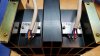
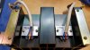
Pioneer SX-980 Output Transistor Upgrade (1).jpg Pioneer SX-980 Output Transistor Upgrade (2).jpg
 
Register to hide this ad
The drivers. Do this with the output transistors disconnected and NOT on the DBT.

Disconnect the outputs, and see that DC balance can be set to 0.000v DC. Until that can happen, nothing else will work. The circuit WILL balance without the output transistors connected.

Then check the emitter resistors (0.5 ohms) and that the base voltages TO the outputs are about +0.6v to the NPN output's base and -0.6v to the PNP outputs base.

Then hook up a dmm to the two base leads, the red to the NPN's base and the black to the PNP's base.

It should read in the vicinity of 1.2 volts and varying the idle current VR1 should cause it to vary up and down a bit.
 
The drivers. Do this with the output transistors disconnected and NOT on the DBT.
Disconnect the outputs, and see that DC balance can be set to 0.000v DC. Until that can happen, nothing else will work. The circuit WILL balance without the output transistors connected.
Then check the emitter resistors (0.5 ohms) and that the base voltages TO the outputs are about +0.6v to the NPN output's base and -0.6v to the PNP outputs base.
Then hook up a dmm to the two base leads, the red to the NPN's base and the black to the PNP's base.
It should read in the vicinity of 1.2 volts and varying the idle current VR1 should cause it to vary up and down a bit.

Hi, Mark. Thank you (again) for such good information! I ended up unmounting all the output transistors from the heat sink to see if I could find out where the popping noises came from. I found one that had arced from the outer edge of the backplate to the heat sink. Apparently, the thermal pads I used weren't quite wide-enough to cover the entire surface of the new output transistors. I ended up using the original mica insulators, but I rotated them 90 degrees, so the backside of the transistors were completely insulated from the heat sink. I'm going to need to source a more-appropriate insulator for the TO-264 cases. Now, on to your procedure:

With the output transistors disconnected, I was able to set VR2 for 0 volts at pin 10 of each amp board. When I measured voltages to the base of each transistor, I ended up with -0.68v on pin 20 of each amp board and 0.54v on pin 15 of each amp board - this was after measuring and adjusting for 1.2v between the bases of each PNP/NPN pair per your instructions. So, the 0.54v to the NPN transistor bases is a little low, but is it acceptable?
 
I've been keeping notes on the receivers I repair, with the Pioneer SX-980 being the most extensive. This may have been published elsewhere on this site, but I'm finding it very handy when doing a preliminary run-through of power supply voltages. I'll check these on each receiver, whether it's functioning properly or not. This list is open for editing - it's kind of a work in progress. For the Pioneer SX-980 power supply, with AC voltages being approximate due to local variances:

Power Supply Voltages
Pin 1 & 3: line voltage from FU1
Pin 2 & 3: line voltage to FU1
Pin 4: ground
Pin 5 & 6: ~75vac supply for 52v rectifier
Pin 6: ~8vac for dial lamps (with pin 29)
Pin 7: +52vdc to power amp boards
Pin 8: -52vdc to power amp boards
Pin 9: ~8vac to FU2 for dial lamps (with pin 6)
Pin 10 & 11: ~100vac supply to FU3 & FU4 for 65v rectifier
Pin 12 & 13: ~36vac to FU5 & FU6 for protection board and 13vdc regulator
Pin 14: ~21vac from FU6 to protection board (with ground)
Pin 15: ground
Pin 16: +13vdc to tuner, speaker switch & protection boards
Pin 17: +13vdc
Pin 18: 7.5vdc (from 13v regulator) to function board
Pin 19: +65vdc to +50v regulator and protection board
Pin 20: 33vdc (from +50v regulator) to tone control board
Pin 21: ground
Pin 22: +50vdc to power amp boards
Pin 23: +23vdc (from +50v regulator)
Pin 24: +23vdc (from +50v regulator) to power amp boards & flat amp board
Pin 25: -23vdc (from -50v regulator) to power amp boards & flat amp board
Pin 26: -23vdc (from -50v regulator)
Pin 27: -50vdc (from -50v regulator) to power amp boards & protection board
Pin 28: -13vdc (from -13v regulator) to speaker switch assembly
Pin 29: ~8vac from FU2 to dial lamps (with pin 6)
Pin 30: ground
Pin 31: unused
 
I went ahead and connected up the output transistors, allowed the receiver to warm up for 10 minutes, then adjusted the DC offset and bias. Everything adjusted out fine and I have audio output from both channels. Upon cold power-up, I'm seeing about 30mV in the right channel and about 10mV in the left. As the receiver warms up, they both dwindle back town to 0v. Is the 30mV in the right channel at cold power-up anything to be concerned about?
 
No, not really - but if it crossed my bench as a paying job, I would chase it as a matter of personal curiosity.

30mV to 0mV
versus
10mV to 0mV
Watch the power supply regulated voltages. See if cooling PS (fan, NOT freeze spray!!) affects it appreciably

Q5 would probably be where I started first, it dissipates a bit of heat. Go to a to-126 that's heat sinked.
Then, if it persisted, I would match a pair of Q1 A992's along with a Q2 c1845.
 
Sorry for the late reply. I'm keeping this particular receiver for myself - aesthetically, it's one of the nicest I've had the pleasure to work on - the cosmetics are very pristine. As I've done in the past, I'll probably come back around to this one when I have time and chase down the measurements I'm getting prior to warm-up. I've got others I need to work on, so I'm diverting my attention to those, for now. I have another SX-980 in the shop that the seller claims has been blowing fuses but, thankfully, not the main fuse, so I'm hoping the output transistors are okay and it's just a typical power supply problem. Mark, thank you, again, for your help!
 
I am looking to purchase a Pioneer SX-980 now that my SX-780 project is complete but became hesitant when I heard the output transistors were unobtainium. After reading through this board it appears that they can be replaced with MJL3281A and MJL1302A. I also noticed that the originals had a CEBC configuration while the replacements have a BCE pinout. As I review the schematic it looks like only 3 pins are used, I assume these should work, but being new to this I do not want to make assumptions. Since I really like the receiver, I wanted to find out if these will provide similar sound and what changes would be needed to make these substitutions work. I will try to find a unit with both transistors working, but if the solution is viable, I plan to buy replacements to keep in stock should the transistors go bad. If there is a better option, please advise.
 
Last edited:
I am looking to purchase a Pioneer SX-980 now that my SX-780 project is complete but became hesitant when I heard the output transistors were unobtainium. After reading through this board it appears that they can be replaced with MJL3281A and MJL1302A. I also noticed that the originals had a CEBC configuration while the replacements have a BCE pinout. As I review the schematic it looks like only 3 pins are used, I assume these should work, but being new to this I do not want to make assumptions. Since I really like the receiver, I wanted to find out if these will provide similar sound and what changes would be needed to make these substitutions work. I will try to find a unit with both transistors working, but if the solution is viable, I plan to buy replacements to keep in stock should the transistors go bad. If there is a better option, please advise.
I don't have an exact count, but it wouldn't be a stretch to say I'd serviced around 50 Pioneer SX-980 receivers and this was (and is) the only one I've ever had to replace the output transistors in. I would just angle for one that looks like it's had some decent physical care and the chances are good the electronics have been cared for, as well.
 
Thank you! That is what I was thinking, but If there is an option for replacement it would be cheap insurance and provide peace of mind. Although not as expensive as the 1080 they are still a good chunk of money for a good one and I don't want to end up with a boat anchor 9 months down the line. So if you can tell me if there are replacements it would be helpful even though hopefully, I will never need to use them.
 
Thank you! That is what I was thinking, but If there is an option for replacement it would be cheap insurance and provide peace of mind. Although not as expensive as the 1080 they are still a good chunk of money for a good one and I don't want to end up with a boat anchor 9 months down the line. So if you can tell me if there are replacements it would be helpful even though hopefully, I will never need to use them.
A quick Google search revealed both are available from online retailers like Mouser and Digi-Key. The part numbers have changed slightly, with the addition of a "G" at the end of each one.
MJL1302A = MJL1302AG
MJL3281 = MJL3281AG

From the datasheet for both, the additional "G" at the end indicates they are housed in a lead-free package so there's no giant change from the older number to the newer number and probably indicative of some new protocol the manufacturer is trying to follow.

Another part that's becoming almost impossible to find is the PA1002 IC that's involved the the tuner FM muting circuit, but there are replacements available from folks here on AK who've actually invented them, as well as at least one vendor on eBay. I've stockpiled enough of the original ICs to hopefully last me the rest of my life. Another IC is the PA3004 in the protection circuit - there are less and less of these available all the time but, again, folks here on AK have designed a replacement (that one might still be in the refining stages).
 
Back
Top Bottom