Hello to everyone,
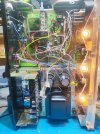
Having spent a lot of hours to our family's old Sx650, time came to introduce myself and reach out for help. Last year I found in the basement our sx650, forgotten since the 90s in exceptionally bad shape, all boards without cables, missing transformer, everywhere soldered various capacitors resistors, a complete mess. Since no one who deals professionally with restorations would like to even open the box with the dirty dismantled sx650, I decided to give it a go without even having basic knowledge.
During 2024 I visited in almost daily basis the Audiokarma forum and read about restorations etc..So here I am and below you will find the results.
-Since nearly all components were already changed, mostly with wrong value parts, I started with blank boards.
- bought everything from Mouser based on BOMs found here
-it is a model sx650 model s, 220 ac Europe, without the extra boards on phono stage.
-replaced everything based on threads from members like Markthefixxer, merlynski, goat67 and several others I forget their names.
-unfortunately all parts were already changed in the tuner board back in the day
-all resistors - capacitors - diodes - transistors have been changed , most were wrong values / toasted
-redid all the wires from the beginning based on the schematic and photos
-i am scared to show how it was before as I have never seen such a mess on internet before ( but I will show eventually because it is brilliant)
Now I am towards the end, I think I am in a pretty good state but all work / measurements carried out are with the SP40W out of board, having soldered 330ohm resistors in pin 2-4-6.
All measurements are steady, it is a week now that I keep turning the Sx650 on and the relay clicks in 5 seconds, I have measured dc offset like echowars said and I am in 17mv-20mv in left-right channels.
- the DBT has a 43watt halogen (around 80watts equivalent) , I saw that it chokes voltage, it is a week now that I have the Sx without DBT and everything is ok. All data is with DBT / without DBT. I now have 70w halogen, not measured something yet.
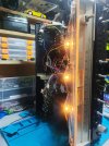
-All cables are properly soldered but aren't attached on the clips as I got tired taking out the GWH-GWR boards all the time, now cables have their own spirit free in the air for repairs. Will attach their proper route when I am done.
The question(s) is the following:
Based on what I measured, in some cases I have more voltage compared to manual, I am afraid to solder the sp40w on board as I do not have the knowledge to "filter" the data I collected.
On other pins values change as soon as I touch the dmm probe, like something is getting charged/discharged and after 2 secs I stop , I already had 2 times a capacitor go boom on my forehead by my mistakes.
If you have time please look at the data and guide me, I am good at listening and doing what I am told at this since I really do not know what I am doing , truly.
If the file is difficult to read or it doesn't open, I will make it again.
The only thing that makes me keep trying on him is that I remember this Sx650 on the living room playing Pink Floyd since I was in kindergarten so I really want to listen to him on my house, don't know how it ended like that but right now it's shiny clean and I really can't wait to listen to .
Thank you and sorry for the long post!
Will answer everything as fast as I can,
Stefanos
Having spent a lot of hours to our family's old Sx650, time came to introduce myself and reach out for help. Last year I found in the basement our sx650, forgotten since the 90s in exceptionally bad shape, all boards without cables, missing transformer, everywhere soldered various capacitors resistors, a complete mess. Since no one who deals professionally with restorations would like to even open the box with the dirty dismantled sx650, I decided to give it a go without even having basic knowledge.
During 2024 I visited in almost daily basis the Audiokarma forum and read about restorations etc..So here I am and below you will find the results.
-Since nearly all components were already changed, mostly with wrong value parts, I started with blank boards.
- bought everything from Mouser based on BOMs found here
-it is a model sx650 model s, 220 ac Europe, without the extra boards on phono stage.
-replaced everything based on threads from members like Markthefixxer, merlynski, goat67 and several others I forget their names.
-unfortunately all parts were already changed in the tuner board back in the day
-all resistors - capacitors - diodes - transistors have been changed , most were wrong values / toasted
-redid all the wires from the beginning based on the schematic and photos
-i am scared to show how it was before as I have never seen such a mess on internet before ( but I will show eventually because it is brilliant)
Now I am towards the end, I think I am in a pretty good state but all work / measurements carried out are with the SP40W out of board, having soldered 330ohm resistors in pin 2-4-6.
All measurements are steady, it is a week now that I keep turning the Sx650 on and the relay clicks in 5 seconds, I have measured dc offset like echowars said and I am in 17mv-20mv in left-right channels.
- the DBT has a 43watt halogen (around 80watts equivalent) , I saw that it chokes voltage, it is a week now that I have the Sx without DBT and everything is ok. All data is with DBT / without DBT. I now have 70w halogen, not measured something yet.
-All cables are properly soldered but aren't attached on the clips as I got tired taking out the GWH-GWR boards all the time, now cables have their own spirit free in the air for repairs. Will attach their proper route when I am done.
The question(s) is the following:
Based on what I measured, in some cases I have more voltage compared to manual, I am afraid to solder the sp40w on board as I do not have the knowledge to "filter" the data I collected.
On other pins values change as soon as I touch the dmm probe, like something is getting charged/discharged and after 2 secs I stop , I already had 2 times a capacitor go boom on my forehead by my mistakes.
If you have time please look at the data and guide me, I am good at listening and doing what I am told at this since I really do not know what I am doing , truly.
If the file is difficult to read or it doesn't open, I will make it again.
The only thing that makes me keep trying on him is that I remember this Sx650 on the living room playing Pink Floyd since I was in kindergarten so I really want to listen to him on my house, don't know how it ended like that but right now it's shiny clean and I really can't wait to listen to .
Thank you and sorry for the long post!
Will answer everything as fast as I can,
Stefanos