• The move to the new server is done. There are some software and database maintenance updates in process. This has us passing the hat around to help out. We appreciate any donations. Seriously, even a dollar helps. The payment page may be found here - https://www.audiokarma.org/support.html

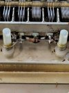
Pioneer tx-9500ii need help identifying resistor value on AWB-023-0 Please

lopezluna

Active Member
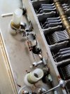
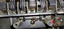
Hi, I recently purchased a pioneer tx-9500ii that is not receiving FM stations. After removing cover for AWB-023-0 I saw a resistor that looks to have a piece missing. I have looked at the schematics but the schematics are way small and I can't find the resistor to identify the value. Can anyone please help me identify the value of the resistor? Much appreciation for any help. Thanks
 

Attachments

  • 20241208_213231.jpg
    20241208_213231.jpg
    126.2 KB · Views: 29
  • 20241208_213018.jpg
    20241208_213018.jpg
    121.3 KB · Views: 27
Register to hide this ad
Can anyone with a Pioneer tx-9500ii tuner help me figure out what resistor value is under the cover of boards AWB-023-0 please? My resistor is broken on right side and can't see the color bands. Please see pictures wich show the resistor in question. Thanks in advance
 
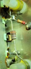
I removed the cover of my TX-9500II last night and tried to identify that resistor. The color code (as best as I could tell) was orange-black-grey-gold, which indicates a 3G ohm value (that's a 3 followed by 9 zeros). It was worn on the top side so it wasn't very obvious. The smaller resistor connected to it was red-red-orange-silver = 22K ohms.

I tried but couldn't locate that resistor on my TX-9500II wiring diagram. I thought the 22K resistor connected to one leg might help me locate it, but it did not, and I've been using schematic wiring diagrams for a VERY long time. And for some reason the copy of the service manual I have, which isn't very good quality, does not include the underside tracing layout for that AWB-023 board - so that couldn't help me either. Perhaps all the details of that specific board in the SM were deliberately omitted by Pioneer back in the late 1970's because that tuner had some cutting edge FM tuner design features?


20241215_210352.jpg
 
@Shikaka I appreciate you looking into it. Mine doesn't have the 22k resistor and no traces of there having one been there. But with your help I can confirm it's orange-black-grey-gold. Thank you very much for your time and help
 
Try to Identify what component it is in the schematic. It’s possible that it is an inductor and not a resistor although it looks like a carbon comp. resistor.
 
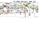
It is most likely a 0.3 picofarad capacitor C4 coupling two tuned circuits that have no dc on them.


mosfet Q1 is fed dc power (red 12.4v ) through T2, and amplified rf comes out the secondary of T2.
be sure the two 3SK45 mosfets have their 2.3 volt biases (orange).

Next come two tuned circuits (blue) that have no dc on them. Fed by T2 secondary
and coupled by C4 0.3 picofarad capacitor (purple) , the second tuned circuit then feeds Q2.

Yellow highlights RF flow path.

Lack of DC voltage far more likely your cause. Stone cold silence, RF LOVES to sneak past things.

Note:: on variable tuning cap, lots of fins means AM, few fins is FM.

You can tack a sub 1 picofarad cap across C4 to test, do not do anything to C4 and ONLY if the DC voltages are good.


Front end annotated.jpg
 
Last edited:
@Shikaka I appreciate you looking into it. Mine doesn't have the 22k resistor and no traces of there having one been there. But with your help I can confirm it's orange-black-grey-gold. Thank you very much for your time and help
The colors are probably orange-black-silver-gold. At 0.3pF this is an extremely small capacitance, nearly impossible to accurately measure with typical home lab equipment. It may be very hard to find a replacement. Chances are that the capacitor is fine and should not be touched.
 
I believe Mark is absolutely correct (as usual), and @rcs16 was right that it isn’t a resistor – even though it looks like one. I stopped looking last night after I couldn’t find a 3G ohm resistor on the wiring diagram for AWB-023.

My first TX9500II I bought new in 1978, but I got a 2nd unit a few years back at a good price and have recapped both. I just checked that 2nd unit, and by identifying the surrounding components, and comparing them to the wiring diagram, I can’t see it being anything but C4 (0.3 pF). But both my units also have that same 22K resistor from one leg to ground, which doesn’t appear on the wiring diagram. Build dates for these units are 11/1977 and 4/1978, so I suspect it was a design change after the wiring diagrams were finalized.

This “resistor impersonator” has a gold 4th band in the 1st unit but the 4th band is silver in the 2nd unit (photo attached). And the 4th band on those 22K resistors were also reversed.

20241217_181926.jpg20241217_193624.jpg
 
Last edited:
Back
Top Bottom