• The move to the new server is done. There are some software and database maintenance updates in process. This has us passing the hat around to help out. We appreciate any donations. Seriously, even a dollar helps. The payment page may be found here - https://www.audiokarma.org/support.html

Pionner SX-626 Output coupling caps

AudioFab

New Member
Hello everyone! I'm a new user of this website, and I must say I love it! It's been VERY useful for a lot of my audio projects! Hope you can help me with this case :

I'm planning to recap my 626 recently bought on Ebay. Since I realized that this little receiver is built like a tank and sounds remarkably good for its 45 years of service, I decided to recap the whole system except the tuner.

But I'm not very at ease with capacitor coupled amplifiers, and I honestly don't know which capacitor would do the best job as a replacement of those two 2 200UF 35V caps. I had some very nice results using Elna Silmic II in the signal path of my other amps (and panasonic FC for the rest), but I never tried to use them for this specific purpose.

Thanks! :)
 
Register to hide this ad
Hi, l have no experience with the 626 specifically but l have had good results with the Nichicon KZ muse in this position, l would think the Silmic II you have been using would be a great choice also.

I have just looked for the KZ and the Silmics/Cerafines and it appears they don't come in that value so maybe a Nichicon fine gold 2200uF 35v would suit that position well but someone else may have a better suggestion.
 
Thanks for your help, Oldsansui :)
If we consider that every other capacitor that carries the signal in the preamp, control amp and the power amp are Silmic II, do you think that the output caps will make a noticeable difference? Right now, I have at home some Nichicon UPW, Low leakage (0.03 CV of 4 uA), low impedance caps that I could use...

And what about metalized polypropylene caps? I have two Vishay MKP1839 axial capacitors. The thing is : they're only 2.2 uF, instead of the original 2200 uF. Will I lose some depth in the low frequencies?
 
Last edited:
A 2.2uf will not work as a Filter or output coupling cap in place of a 2,200uf cap.

I would use a UPW or UKL 3,300uf 50v cap for output coupling caps. Some guys go as high as 4700uf, but 100% to me is a bit excessive. This is based on all of the CEA type lytics' in the amp board. If you want to go low noise(CEANL) use the UKL. The reason for the voltage increase is to gain some voltage headroom due to todays higher wall voltage, and subsequently slightly higher rail voltage. Schematic shows 26V just before the + side of the cap but I'd wager that the voltage with todays wall voltage is going to be closer to 30 or 32. A 35V cap will be right on the edge of it's performance envelope.

Originally Posted by markthefixer
UPW and UHE from Nichicon is the general purpose e-cap series I usually recommend. Yes, they are 105 degree c caps.
There are Panasonic caps EchoWars recommends as well, they are fine. (EDIT: FC's predominantly)

THEN there are the low leakage caps, which is some circuit locations DO make a difference. They ARE literally QUIETER.
They are the unique Nichicon UKL series, which was originally just an 85 degree c cap line.
Now there are UKL's that are 105 degrees c rating.

When examining the recap lists (especially the ones I personally did) You will find MANY UKL caps in them.

My "rules of thumb" for caps:
Quote:
Rule of thumb: 0.1uf to 1.0uf of any type >> stacked film DSF(cornell dublier) or ECQ (panasonic)caps
cea >> nichicon upw or uhe caps
ceb > nichicon tvx axial caps or holler for help on these
ceanl, cssa, csza >> nichicon UKL caps - (low noise, low electronic leakage)

It didn't cover non-polarized (or "bi-polar") caps, there are a few, but I can't look up that answer now at this computer about which Nichicon series to use.

The "stacked film" caps are being discontinued in some convenient voltages, but regular ecq's will do.
 
Yes go with what Larry suggests as he is much more experienced than me, he was a great help with one of my projects. l think going to a 50v cap is a good idea, this is what l usually do also, its just that the none of the audio grade caps we were talking about seem to come in your value at 50v, closest being 2200uF 35v.
So yes go with the UKL's.
 
I have recently recapped a SX-3000. This is a SX-626 but sold in American army stores in Europe I believe.
Changed the stock 2200µF 35V by 3300µF 35V Nichicon KS. KS is similar to Nichicon KG but smaller , so better to put it on the the board. and they fit exactly.
http://www.nichicon.co.jp/english/products/pdfs/e-ks.pdf

Remark: The original caps had two negative leads fitted on the board. Replacement just one so I had to make connection to second negative solder joint with a piece of wire.

I'm happy with the result.
PIO_SX3000_FR.jpg
PIO_SX3000_TOP.jpg
 
Last edited:
Thanks for the advice! :)
The whole recap is done, but I noticed that Q9 was producing excessive heat after a few minutes...
When I look at the voltage on the collector of Q11, I only get around 3V instead of the 26V suggested in this thread...
When I put my headphones (I hesitate to plug my beloved speakers right now...), I hear that one channel sounds lower than the other...
Also, the bias measured with the white lead taped on the output caps give me the suggested 17 mv for the right channel but 160 mV for the left one!! I tried adjusting VR3 without any success (it goes from 300 mV to 160 mV minimum..)
In other words.. help!!!
 
Cap coupled amps require a LOAD (speakers or dummy loads/ high wattage (>50w) resistors) connected to the speaker terminals BEFORE you do adjustments. Grab a couple of cheap disposable 8 ohm speakers, connect them, and do the adjustments with the volume at ZERO.
 
Oh ok! I redid the test with a pair of speakers tonight. Same problems with the left channel :(
The right channel plays well, and when I plug the preamp directly into my other amplifier, the sound is perfect.
The two amplifier's fuses are still OK, but as I said, when I touch the heatsink a minute after I turned on the receiver, I realize that Q9 (one of the 4 power transistors) gets really hot compared to the three others.
Also, the left channel produces some random "pop" sounds in the speaker even if the volume is at minimum.
I heard that the trim pots are very delicate on those amps.. Do you think that this issue can be solved by changing the four trimmers?

Thanks a lot, I appreciate your help! I look forward to hear this old buddy again! :music:
 
Something is causing Q9 to heat up excessively. trimmers aren't the problem if they are reading a steadily increasing or decreasing number when tested. How ever the trimmers in pioneer gear aren't the best stuff out there either. You can put new ones in, but it's not going to solve your problem. I'd start checking for out of spec resistors on that channel and comparing the readings with the other channels mirror part. Also pull Q9 and do Echowars 6 way diode testing on it. That'll get you started.
 
OK! Thanks for the advice! New update : I let the good channel run with some speakers and a source at low level for about 30 minutes. I removed the fuse of the bad channel then I decided to reinstall it to see if something has changed. No more pop sounds, but the bad channel plays significantly lower than the good channel. I begin to suspect that those old 2SC793 power transistors may be defective. I'll try to remove and test them. My multimeter has the diode mode to test some transistors.
 
By all means check the output transistors for peace of mind but when they fail they often fail short and blow the protection fuse for that channel. l would be looking more at the pre-driver and driver transistors for that channel, in your case q1, q3, q5 and q7 especially if you cant set bias and have dc offset issues. There are many threads here on Audiokarma with regard to testing NPN and PNP transistors. Atleast you have identified the problem to be on the main amp board forward as you stated when using as a pre-amp only no problem exists.
Let us know how you go.
 
OK! :)
New update : I removed and tested the four transistors and found noting especially wrong. Every transistor shows about 0,45 to 0,5 volts. I also installed the new trimmers.
But I still have the same issues...

so I'll probably change every semiconductor on that amp board. I think they probably have served their time. I'll let you know when it's done!
 
Don't arbitrarily shotgun the transistors. Some of them are hard to find replacements for. Best is to 6way test them and reinstall if ok. I would look more at the other parts (resistors, caps, diodes, etc) before the transistors. You ARE getting sound which tells me that they are working, but aren't getting the signal they need. Check the boards for 2sa725, 2sa726 and 2sc1451's. These 3 are MUST CHANGE as they have a bad history of breaking down and causing at minimum what sounds like Rice Krispies(all 3) and at worst (the 1451)a blown board.(This is on any pioneer they are in, not just the 626.) The 725's and 726 will be on most of the boards if it has them, and the 1451 will be on the amp board only. I've heard and seen the extremes of all 3 #'s, where they would start breaking down within a year of manufacture, or the other end are working fine after 40+ years. The majority have died or broken down already. The chances of an existing 725,726, and or a 1451 being bad here is real high.
 
OK, thanks for your precious help, Larry! :)
I'll remove and test every transistor on that board tonight. Fortunately, there are no 725, 726 or 1451 on the power amplifier board. Only some 2SA497, 2SC497, 2SC983 and 2SC732. The only thing is... I intend to use this amplifier daily and I'm scared to find out, in a few months (years) that those old transistors have finally failed... I know pretty much about how caps grow old, but I have no experience how transistors behave over time.

PS : I found some 2SA725 on the control amplifier. They appear to work fine (since I tested the preamp output without any problem). I'll consider changing them soon.
 
Hello everyone! I finally had time to work on my 626. Since I had not the time to troubleshoot the whole thing one part by one, I changed every semiconductor on the power amp board. I finally found the guilty part : the STV-3 rectifier on the left channel. That's why I wasn't able to adjust the voltage with VR2 to get my 26V.
Anyways, the result is pretty impressive!!! very warm and powerful! From Led Zeppelin to Norah Jones or Diana Krall, I love it!
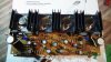
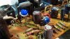
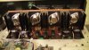
Here are a few pictures of my job! !
SAM_0096.JPG
I also changed these 4 0.5 Ohm resistors because the old ones seemed really worned
SAM_0099.JPG
Here are the trim pots
SAM_0100.JPG

Thanks to several people on this website who helped me with this awesome project!
 

Attachments

  • SAM_0101.JPG
    SAM_0101.JPG
    66 KB · Views: 16
You PM'd me about the 2sk30 JFETS in the awg-008 control amp.

UNTIL you have PROVEN one is bad, by swapping ONLY the jfets between channels and have the problem MOVE to the OTHER channel, never assume they are bad.

http://ampslab.com/trans_2sk30atm.htm
check with the members as to whom have bought these from ampslab.com and have a few spares.

I wasn't kidding with my tagline about me being on hiatus - I'm dealing with my father's estate, emptying his house and preparing it for sale after his surprise demise.
 
Last edited:
Back
Top Bottom