• The move to the new server is done. There are some software and database maintenance updates in process. This has us passing the hat around to help out. We appreciate any donations. Seriously, even a dollar helps. The payment page may be found here - https://www.audiokarma.org/support.html

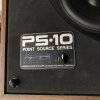
Poking around Design Acoustics PS-10A

Wombaton

Active Member
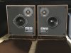
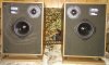
Got these recently and am trying to make them work as they should.
Testing the sound shows that the tweeters are mostly asleep -- not fried, but not playing as they should either, regardless of the position of the HF adjustment pot.
I have a number of various questions about cleaning and restoration, but will post them as individual messages (within this thread), as that should make it easier for people to comment on them.

IMG_0867.jpg
 
Last edited:
Register to hide this ad
Question 1: cleaning the pesky HF adjustment pot

Yep, this thing:

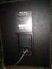
View from the front:
IMG_0958.jpg


View from inside the cabinet:

IMG_0957.jpg


Just wondering about the best way to clean it. Should it ideally be removed from the cabinet and disassembled, or can I just spray deoxit through the slits on its back cover without detaching it from the board?
I already tried to wiggle it a bit, as well as its knob / handle out front, and it does not look like things are going to come apart with ease.

Always grateful to see any advice,

W.
 
That pot is an L-pad. If the HF cuts out or you hear scratching noises when the L-pad is adjusted, then it definitely needs cleaning. I would first spray DeOxit to clean it and then follow up with FaderLube to lubricate the moving parts. The decision to remove from cabinet or clean in place is more on how much work you want to do. I would clean in place, ensuring that any overspray and drips are captured and prevented from soaking into the cabinet. Also, allow time for the solvents to totally evaporate before closing up the cabinet.

If the sound from the tweeters is weak and you do not hear any cut-outs or scratching when adjusting the L-pad, then I would suggest replacing the caps as the first option.

PS: Rather than create multiple threads for restoring one set of speakers, I suggest keeping your questions to one thread. It avoids overlapping information and cuts down on the noise when others search for info in the future.
 
@RTally: THX for the advice, as usual! Re PS, everything should be contained in this single thread. I only meant that I will post my questions as separate messages within this thread, rather than posting one long message with many questions.

I will clean the L-pad in place first, just to be thorough and eliminate it as a suspect, but I believe that my problem with HF may go deeper than that.
It seems that the original coating on the tweeter domes is starting to disintegrate, so @CraigVMN is not wrong with his comment.
I actually got a pair of replacement tweeters inexpensively off eBay, but these are not original PS-10 stock.
They have similar specs and exactly the same form factor, so that they bolt to original tweeter plastic covers perfectly.
The main difference is that their diaphragms are Ti-infused.
The seller commented that these tweeters were made by the same (tonegen) factory as the original ones.
Since these replacements were inexpensive, I am willing to experiment with them and check out how the speakers will sound.

Changing the capacitors is a possibility and a subject of my next question.

Here are some photographs.

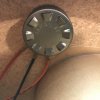
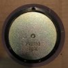
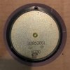
An original tweeter, P/N 10153 (163TNL), front and back:

IMG_0963.jpg

IMG_0961.jpg

And here is the intended replacement, P/N 5DR53061 (453TND), front and back:

IMG_0964.jpg

IMG_0962.jpg
 
Last edited:
Question 2: the crossover insanity

Here is what I got sitting inside:

IMG_0966.jpg

1x 10 uF
1x 14 uF
2x 165 uF

All of these are +-20% and 50 VDC. Now, I can easily replace the 10 and 14 uF ones with Dayton film, but is there a reasonable way to handle the insane 165 uF ones? Replacing both of these with film caps will set me back at least $80 per speaker, which is overkill IMO. The only frugal option I see is replacing with new electrolytics. Actually, for each old 165 uF cap, I can do two 330 uF electrolytics connected in series. That should give me exactly 165 uF total capacitance (within reasonable tolerance) and it should decrease the response asymmetry, compared to using a single polarized electrolytic cap.

I would appreciate any thoughts here. Am I completely bonkers considering the electrolytic route?
Another option is, of course, to check these caps and just leave them alone if they are still roughly within spec.

THX,

W.
 
Except for intellectual curiosity, measuring crossover caps is a waste of time, particularly if you are not measuring ESR at audio frequencies. Caps need to be removed from the circuit for testing. Since most caps are not that expensive, you might just as well reinstall new ones instead of the old ones.

The electrolyic caps definitely need to be replaced. The PS-10a was sold in 1991. (See Oct. 1991 issue of Audio for info.) 30 years is old enough for electrolytic caps to degrade. I prefer using poly caps to replace electrolytic caps.

Based on the FR graph in your pics, I assume that the 165 uF caps are part of a 2nd order filter for the woofer and the mid, that is, one of those caps is in the direct signal path of the mid and the other is across the woofer VC.

I prefer not to spend more on caps than the speakers are worth. For these speakers I would use electrolytic caps for the large values and poly caps for the smaller values. I would use parallel 80 uF electrolytic caps for each 165 uF cap. The 5 uF difference is close enough and only 3% off from the originals. Or maybe parallel 68 and 100 uF caps for being slightly closer to original value. Generally, crossovers are not that precise so it I would use whatever is close and available.

If you are going to use electrolytic caps, you should be using non-polarized electrolytic caps, not polarized ones. Also, I would not series connect electrolytic caps because that will affect voicing. Series caps increases ESR, which is higher for electrolyic caps than poly or film. Using poly caps will make the tweeter slightly brighter and doubling the electrolytic for the mid will slightly attenuate it. Paralleling electrolytic caps will half the ESR, bringing it closer to the poly ESR and thereby affecting the mid and tweeter less different.
 
I have two pair of those, one pair I bought new years ago when a local hi-fi store went out of business, the other pair I picked up at a flea market for $10 a few years ago. The tweeters are not very powerful, they never were. They do have good balanced sound though. A lot has to do with positioning in the room. Both pair of mine came with tallish stands that put them up off the floor about ear height while sitting.
I had basically grabbed the second set because the seller told me he replaced both tweeters more recently. I wanted to see if they were better or worse than my original pair.
The second set was only slightly brighter than my older pair. I went ahead and recapped them with all new caps from Parts Exp. In the end, I really didn't hear much of a difference. I didn't a/b the first one vs. an original but the change was likely so minor I never bothered to do my first pair, which I actually seem to prefer for longer listening periods.
At the moment, I don't have neither set in a system, I regularly swap things up or try different speakers, but I will say I like them enough that they're in my keeper pile. I also picked up a water damaged pair for parts a while back off CL in a package deal, they're probably fixable but the grills and lower plates are shot.
I had to re-foam the woofers on my original pair twice now, the first time was after about 8 years, the last time was four years ago. The second pair were already done when I got them.
 
This is turning into an interesting discussion, the likes of which you usually see in the 'vintage amplifiers' forum.
Any capacitor introduces some distortion to the signal path, but the general rule is that any film capacitor is much better (less distortive) than any non-polar electrolytic, while any non-polar electrolytic is in turn better than a polar electrolytic. For the latter, that is the consequence of the manufacturing process, which makes the positive and negative sides asymmetric.

However, my understanding is that by combining two identical polar electrolytics in series (as - | | + -- + | | - ) one can greatly reduce the asymmetry and effectively get a compound non-polar cap with 1/2 capacitance. I did not factor ESR into this thought, assuming that it will be pretty low for new caps. I may be mistaken, but my impression is that non-polar electrolytics are actually made that way.

Of course, ESR would be much lower for the parallel connection, but for that one it is also usually recommended to use either identical capacitors, or
a small-large capacitance pair. So, a 2x 80 uF non-polar pair would work and so would something like 150 + 15 uF. A 100 + 68 uF pair seems to have a different kind of asymmetry (non-identical components), but it is the only option realistically available, as the assortment of capacitances for non-polar electrolytics is not that wide. According to Mouser and Digikey: no 80 or 150 uF (or similar values), one option for 68 uF with not so great VDC rating of 50 V (Nichicon UDB1H680MRM), plenty of options for 100 uF only.

So it is either this pair in parallel, or cooking up a makeshift non-polarized cap out of two polarized 330 uF ones (plenty of options as well).
If cap ESR is the more important factor for the crossover, parallel arrangement it is. Measuring relative distortions of these two possible arrangements at all possible signal frequencies would be an interesting scientific experiment, but I think I will pass for now :)

@RTally: sorry I was not clear, when I refer to 'capacitor testing,' I automatically imply that it is done out of circuit. For ESR, I only have a simple tester that cannot trace it as a function of frequency. But that is what most of us have as I would assume.
 
Both pair of mine came with tallish stands that put them up off the floor about ear height while sitting.

That sounds like a really bad idea. These were designed to take advantage of the floor for bass emphasis - like a Pressure Zone Microphone in reverse. Just getting them off of carpet and on a solid surface makes a HUGE difference. Putting them on stands might get the HF at ear level, but wouldn't allow them to make bass like they should.
 
I would actually test out the tweeters before trashing them and replacing. They might not be the issue... Bypass the L-pad and see what happens...
 
That sounds like a really bad idea. These were designed to take advantage of the floor for bass emphasis - like a Pressure Zone Microphone in reverse. Just getting them off of carpet and on a solid surface makes a HUGE difference. Putting them on stands might get the HF at ear level, but wouldn't allow them to make bass like they should.
I respectfully disagree. I made stands for mine, about 30 inches tall, and there was no shortage of bass at all. Just place them close to the wall, plenty of surface to reflect the low frequency.
Link to the stands I built.
https://audiokarma.org/forums/index...speaker-stands-im-going-to-build-some.457303/
 
Last edited:
Except for intellectual curiosity, measuring crossover caps is a waste of time, particularly if you are not measuring ESR at audio frequencies. Caps need to be removed from the circuit for testing. Since most caps are not that expensive, you might just as well reinstall new ones instead of the old ones.

The electrolyic caps definitely need to be replaced. The PS-10a was sold in 1991. (See Oct. 1991 issue of Audio for info.) 30 years is old enough for electrolytic caps to degrade. I prefer using poly caps to replace electrolytic caps.

Based on the FR graph in your pics, I assume that the 165 uF caps are part of a 2nd order filter for the woofer and the mid, that is, one of those caps is in the direct signal path of the mid and the other is across the woofer VC.

I prefer not to spend more on caps than the speakers are worth. For these speakers I would use electrolytic caps for the large values and poly caps for the smaller values. I would use parallel 80 uF electrolytic caps for each 165 uF cap. The 5 uF difference is close enough and only 3% off from the originals. Or maybe parallel 68 and 100 uF caps for being slightly closer to original value. Generally, crossovers are not that precise so it I would use whatever is close and available.

If you are going to use electrolytic caps, you should be using non-polarized electrolytic caps, not polarized ones. Also, I would not series connect electrolytic caps because that will affect voicing. Series caps increases ESR, which is higher for electrolyic caps than poly or film. Using poly caps will make the tweeter slightly brighter and doubling the electrolytic for the mid will slightly attenuate it. Paralleling electrolytic caps will half the ESR, bringing it closer to the poly ESR and thereby affecting the mid and tweeter less different.
It was actually earlier, 1983-4. My brother bought a set when they first came out.
 
I have a pair but without any adjustment. I replaced the 10" woofer because of rot. These actually sound pretty good as they are but need to be on stands.

3.jpg 6.jpg 7.jpg
 
I worked at the original Design Acoustics in Torrance, California before it was sold to Audio-Technica who introduced the PS series speakers. I have never heard any of the PS series speakers but I did buy a used pair recently of the DA-10/LDM satellites that originally came as part of system with a separate woofer box. These satellites use the same midrange driver as the PS-10 paired with a Peerrless K010DT soft dome tweeter. I just wanted to comment that the Audio-Technica Japan sourced midrange driver sounds much better than I was expecting. With a plastic frame and a treated paper cone with a rubber surround my expectations were moderate but that driver is a very good extended range midrange driver with very good treble frequency extension. I yanked the stock cross-overs out and run the mid drivers full range with just a new cap on the Peerless tweeters and they sound very good. I just wanted to add my two cents worth to this interesting discussion thread.
 
Dear All,

I would like to thank everyone (as usual!) for contributing to this thread and offer a little update.

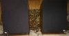
1. L-pad cleaning: I was able to pop off the metal caps with louvres covering the L-pad backs [see second image in post #2 above]. Without the cap, all the L-pad innards are exposed and it becomes easy to spray whatever you need inside.

IMG_0988.jpg

As can be observed from this photo, the L-pad insides do not look so bad. I saw no signs of dirt, corrosion or other deterioration.

2. Tweeter replacement: with L-pads cleaned, I went ahead and replaced the original tweeters with the 5DR53061 (453TND) ones [see post #5 above].
That made a big improvement in the sound quality. HF is now present as it should be and adjustable by the L-pads.
Naturally, I need to listen to these speakers a bit more, but on my first test run I did not hear any obvious flaws.
BTW, these tweeters are for Mirage speakers, but in the case of PS-10 they seem to be a good replacement:
https://reconingspeakers.com/product/mirage-5dr53061-tweeter-m-890i-m-895i-m-1090i/

Here is how the speakers look like with these tweeters installed [tested with Kenwood KA-5002]:

IMG_0992.jpg


3. Crossover recap: it looks like Parts Connexion has better availability of audio capacitors, compared to my usual sources. They seem to have bipolar electrolytics [Jantzen] with capacitance I need to replace the 165 uF ones. I can also use Jantzen film to replace 10 and 14 uF, but essentially every original capacitor will have to be swapped for a symmetric pair. Since the crossover board is rather small, I wonder if I could mount one new capacitor in the pair over the board (i.e., same as the original one) and the other under the board? Then I can glue in some supporting wooden beams and attach the crossover board to them to make sure none of the new capacitors are getting crushed or stuck to something.

Wmbtn

 
Last edited:
Dear All,

I would like to thank everyone (as usual!) for contributing to this thread and offer a little update.

1. L-pad cleaning: I was able to pop off the metal caps with louvres covering the L-pad backs [see second image in post #2 above]. Without the cap, all the L-pad innards are exposed and it becomes easy to spray whatever you need inside.

View attachment 2023692

As can be observed from this photo, the L-pad insides do not look so bad. I saw no signs of dirt, corrosion or other deterioration.

2. Tweeter replacement: with L-pads cleaned, I went ahead and replaced the original tweeters with the 5DR53061 (453TND) ones [see post #5 above].
That made a big improvement in the sound quality. HF is now present as it should be and adjustable by the L-pads.
Naturally, I need to listen to these speakers a bit more, but on my first test run I did not hear any obvious flaws.
BTW, these tweeters are for Mirage speakers, but in the case of PS-10 they seem to be a good replacement:
https://reconingspeakers.com/product/mirage-5dr53061-tweeter-m-890i-m-895i-m-1090i/

Here is how the speakers look like with these tweeters installed [tested with Kenwood KA-5002]:

View attachment 2023718


3. Crossover recap: it looks like Parts Connexion has better availability of audio capacitors, compared to my usual sources. They seem to have bipolar electrolytics [Jantzen] with capacitance I need to replace the 165 uF ones. I can also use Jantzen film to replace 10 and 14 uF, but essentially every original capacitor will have to be swapped for a symmetric pair. Since the crossover board is rather small, I wonder if I could mount one new capacitor in the pair over the board (i.e., same as the original one) and the other under the board? Then I can glue in some supporting wooden beams and attach the crossover board to them to make sure none of the new capacitors are getting crushed or stuck to something.

Wmbtn
They look good and I like that you used the original DA tweeter mounting flanges.
Regarding the crossover, I believe you need no polar caps? Also, as long as the caps are replaced to the proper positions, it doesn’t matter how you do it. Toy can also stack caps on top of each other if space is an issue, but there’s a lot of room I these cabs.
 
They look good and I like that you used the original DA tweeter mounting flanges.
Regarding the crossover, I believe you need no polar caps? Also, as long as the caps are replaced to the proper positions, it doesn’t matter how you do it. Toy can also stack caps on top of each other if space is an issue, but there’s a lot of room I these cabs.

Actually, the gentleman who sold me the 5DR53061 tweeters already had them mounted on the PS-10 flanges (which was a perfect fit). So now I got two spare flanges with all the mounting hardware.

For the crossover, I plan on using non-polar electrolytic caps (2x 82 uF) to replace the 165 uF originals. Currently having some problems getting them from Parts Connexion; they do not have 10x 82 uF in stock. We'll see what tomorrow brings.

As for the capacitor mounting above and below the crossover board, I am not worried about electrical connections, but rather its mechanical integrity. Originally (with all caps mounted above the board), the board is hugging the cabinet side. Now, with stuff mounted on both sides, I figure, the board will be hanging in between two support ribs, or something like that. Could start resonating with some LF excitations from the woofer that will be very close to it. I guess, I will need to pad it at the bottom and try to shield it from the woofer with the filler foam.

Cheers,

W.
 
I respectfully disagree. I made stands for mine, about 30 inches tall, and there was no shortage of bass at all. Just please them close to the wall, plenty of surface to reflect the low frequency.
Link to the stands I built.
https://audiokarma.org/forums/index...speaker-stands-im-going-to-build-some.457303/

Sorry, I also have a profoundly stupid question about speaker stands. It would be applicable to PS-10, but also to many other cases when we need to lift the speakers between ~ 10 and 40" off the floor. In this case, my knee-jerk reaction is to troll the local CL (or visit appropriate stores) for inexpensive used furniture. I.e., a pair of sturdy end tables would lift the speakers ~20" off the floor and possibly have some extra storage space below. A pair of bar stools would lift the speakers ~30" off the floor, which should work for PS-10s. Of course, such furniture pieces could be modified as needed -- spikes to the feet, non-slip covers on top, custom top surfaces, etc.

So is that a reasonable idea, or is my thinking flawed? Has anyone tried doing that with satisfactory results?

THX,

W.
 
Back
Top Bottom