• The move to the new server is done. There are some software and database maintenance updates in process. This has us passing the hat around to help out. We appreciate any donations. Seriously, even a dollar helps. The payment page may be found here - https://www.audiokarma.org/support.html

Polarity Question Old 4000 Mfd caps ?

Gary Mattis

Active Member
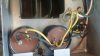
I'm recapping an old Whirlitzer Organ amplifier and power supply. The power supply has two gigantic 4000 Mfd @ 25 WV caps. I am assuming that the red paint on the terminals is for negative sence the ground lug goes to chassis (see pic -yellow wires), please correct me if I am wrong ? , This thing has a 6 inch 4 plate Selinium Rectifier that I do not want going up in my face because I hooked the two 4000 uf caps up backwards. As you can see they are in parellel making it 8000 uf at 25 WV.
 

Attachments

  • IMG_20180314_104203137.jpg
    IMG_20180314_104203137.jpg
    57.1 KB · Views: 34
Register to hide this ad
I wouldn't run for long with that selenium rectifier. It has a failure mode that is unpleasantly noxious, and at this age, failure is eventual and inevitable. Best to replace it with a silicon rectifier and appropriate dropping resistor.

I also wouldn't necessarily assume the chassis is -ve. It usually is, but not always. Power it up and measure the voltages, or check which terminal of the caps is connected to the +ve terminal of the rectifier.
 
I am assuming that the red paint on the terminals is for negative sence the ground lug goes to chassis (see pic -yellow wires), please correct me if I am wrong ?

Well, without seeing a schematic it is hard to say for sure. But, considering 25V rating, it may be those caps are for bias supply (although admittedly pretty big for that). Bias is typically negative so the bias supply capacitors have the positive capacitor terminal grounded.

It is my opinion the red terminal is the positive of the capacitor and this is some sort of negative supply, thus correctly connected with the positive cap terminal to chassis/ground.

Edit: Guess I presumed this was a tube amp, but maybe it isn't. If not, I still think it suggests a negative supply, but not necessarily bias.
 
Last edited:
It looks like they are isolated from the chassis so my guess would also be for the bias supply.

A red dot means positive.
 
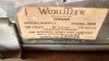
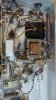
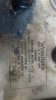
I think I need to give a little more information about what I'm working on , year and model unknown ? but the PS does have a label on it and it, ! (See pics) The amplifier is a 6L6 PP type, 6130 model whirlitzer, there are two transformers and a choke I believe inside of the amplifier itself , I do not know if the negative bias in in the amplifier or is external in the 6230/model action supply - PS ? ( see pics ) . I never tested anything before I shut it off to rebuild it. I knew it was wax caps and did not want to run it for very long.
 

Attachments

  • IMG_20180317_142022074_HDR.jpg
    IMG_20180317_142022074_HDR.jpg
    78.3 KB · Views: 14
  • IMG_20180317_142155997.jpg
    IMG_20180317_142155997.jpg
    50.4 KB · Views: 14
  • 1521311743614-2042759583.jpg
    1521311743614-2042759583.jpg
    41.5 KB · Views: 14
Black transformer is power, smaller one is choke, and the bigger one to the right is the output transformer.

What's the picture at the top of the thread? Doesn't look like anything close to the pics right above.
 
Can you highlight where the caps in the picture in post #1 appear in the picture of the underside of the chassis in post #5?
 
I think that I have a custom built version of a 4600 Electro Static Organ from the late 40's or early 50's , Until I research much further on the operation principles I think I should just put back the two 4000 MFD caps back into the action PS . and re cap the amplifier. These are complicated machines and they work on AC frequency pulses and a windchest with over 100 reeds. The wrong caps in there can throw it out of tune.
 
Black transformer is power, smaller one is choke, and the bigger one to the right is the output transformer.

What's the picture at the top of the thread? Doesn't look like anything close to the pics right above.
That is the action power suppy and the 2 giant cap cans are 4000 mfd each at 25 WV, I decided to put them back in instead of replacing them with 4x1000@50volts for each one because if it is not correct the ac pulse can change and it can put the entire electrostatic organ out of tune. It's not a easy machine to understand the operating principle on , It is a 4600 series model from the late 40's similar to a hammond design in some ways but not the same in the windchest or reeds. The AC pulse is criticle from what I read so far, I need to do some research before I mess with the action PS, I will just recap the amplifier for now and make sure I understand it before I mess with those giant caps. It was working and sounded good.
 
Last edited:
Do you play the organ?

Are you rebuilding an organ or just the amp? I also have several Wurlitzer organ amps and a couple of reed wind boxes from scrap pulls, plus a couple of Hammond tone wheels.

The amp you have there is its own amp with built in power supply. The amp can be pulled and used by itself.
 
That is the action power suppy and the 2 giant cap cans are 4000 mfd each at 25 WV, I decided to put them back in instead of replacing them with 4x1000@50volts for each one because if it is not correct the ac pulse can change and it can put the entire electrostatic organ out of tune. It's not a easy machine to understand the operating principle on , It is a 4600 series model from the late 40's similar to a hammond design in some ways but not the same in the windchest or reeds. The AC pulse is criticle from what I read so far, I need to do some research before I mess with the action PS, I will just recap the amplifier for now and make sure I understand it before I mess with those giant caps. It was working and sounded good.
Ah, I thought you were originally referring to the amplifier power supply, not the tone generator power supply.

The red terminals on the tone generator aka action caps are very likely positive, but I would run it up and measure the voltage at the terminals to be sure.
 
Back
Top Bottom