Hello, my name is Mike Allen, I just recently purchased filter capacitors and power supply board replacement capacitor kit for my Marantz 4140 amplifier. I have a couple concerns, first the minor one, of the five that are soldered to the top of the board, one of the original capacitors designated C806 is a 220 microfarad at 10 V capacitor. The replacement is 220 microfarad at 16 V. I am presuming that slight voltage change is not an issue? My biggest concern is the larger capacitor that hangs from the side of the power supply board that’s connected directly to chassis ground and the transistor on the board. The original is 100micro the new one supplied in the kit is 1000micro. Some of my research says that is a proper upgrade and other research says that will cause catastrophic failure. I’m not planning on replacing anything other than capacitors at this point. Is that 10 times stronger capacitor meant to compliment the new transistor that was in the package that replaces the original thats mounted on the heat sink? Thank you much for any guidance.


You are using an out of date browser. It may not display this or other websites correctly.
You should upgrade or use an alternative browser.
You should upgrade or use an alternative browser.
Power supply board capacitor question on 4140
- Thread starter Mike 4140
- Start date
Register to hide this ad

Good morning, welcome to AK.
I'll try to answer your questions:


I'll try to answer your questions:
1. C806 220uF/16V substituted for 220uF/10V - That is perfectly fine as long as it can physically fit onto the board. Modern capacitors are smaller than 30 years ago so it will most likely be smaller than the original. Going higher in voltage rating is OK, just don't go lower than the original.
2. Original 100uF vs new 1,000uF capacitor - The schematic shows two capacitors near the P800 Power Supply board.
- C005 100uF/63V, attached to terminal H on the P800 and GND.
- C006 1,000uF/63V, mounted on a terminal strip and connected to terminal F on the P800.
- You are correct (according to the schematic) that the one connecting to GND should be a 100uF, but are you sure that that capacitor was not meant to replace C006 1,000uF on the terminal strip?
- Looking at the parts list in the SM, I do see C006, but not C005 (EDIT-found it). How do you know that the 1,000uF in the kit was intended to replace C005 and not C006?
3. Can you post a photo of the instructions where it says to replace C005 with the 1,000uF cap?
Last edited:
Thanks so much for your quick reply. A note on one of the sheets that accompanied the kit says “ the 1000 µF 64 V capacitor is to replace the “axial cap” that’s next to the power supply. Just make sure you put it in the correct way.” what is the axial cap ? I’m not sure where that is or if that meant to describe the one laying next to the power board where the existing 100 microfarad 64 v cap is now. The kit has five can capacitors that mount to the board itself. They all seem right. The only other capacitor that came with the kit was the 1000 mic. There was no 100 mic capacitor included so I assumed that the 1000 was the one that is replacing the 100 that’s there now.
The difference between radial and axial capacitors is where the leads come out.what is the axial cap ?
Here is a picture of both types.

What the instructions say is that you should use the 1000uF/64V capacitor to replace the axial cap next to the power supply.the 1000 µF 64 V capacitor is to replace the “axial cap” that’s next to the power supply. Just make sure you put it in the correct way.”
C006 is a 1000uF axial cap so your 1000uF cap should replace this one, not the 100uF that you stated.
It should be mounted on a stand-off attached to the chassis.


Yes, thank you. That all makes perfect sense now. I guess the only confusion was I was simply short changed the 100 µF cap that should’ve been in the kit that lives right near the power supply board that I was assuming was the 1000. Guess I’ll just purchase that separately someplace, thank you so very much for all your time and help.

Or contact whoever you bought the kit from. Hopefully not hifiaudio / captainfantastic.Yes, thank you. That all makes perfect sense now. I guess the only confusion was I was simply short changed the 100 µF cap that should’ve been in the kit that lives right near the power supply board that I was assuming was the 1000. Guess I’ll just purchase that separately someplace, thank you so very much for all your time and help.

foldthe
Active Member
you can replace the 1000uf axial cap as is but axial caps are generally more expensive. If you follow the red + lead from that cap it actually is connected to the middle of the power supply board. There is an unused hole nearby that is to ground which is perfect for a radial capacitor. I have replaced this cap with a Radial 1200uf/63v UPW Nichicon
I don't have a personal photo but the red wire and the adjacent hole is where the radial cap would go.
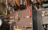
I don't have a personal photo but the red wire and the adjacent hole is where the radial cap would go.
I decided to use the 1000 radial from the kit for the replacement C006 and just fabricated a stable mount. I purchased a 100 mic, 100v on line for the C005 that wasn’t included but thanks for the advice. I didn’t think just replacing the power supply and the large filter caps alone and adjusting bias would improve the bass response this much but it sure has!