• The move to the new server is done. There are some software and database maintenance updates in process. This has us passing the hat around to help out. We appreciate any donations. Seriously, even a dollar helps. The payment page may be found here - https://www.audiokarma.org/support.html

power supply issues on NAD C320 Amplifier

matjo

Member
Dear AK friends,

A friend of mine brought a couple of NAD amplifiers (C320 and C370) with issues.
Although I am more a Sansui-Guy, I just thought I would give it a try in finding out the problem.

Tee C320 does not turn on at all, so I thought that would be the easiest one...... but I am lost already.

What I have checked so far:

No DC-voltage from Power board to mainboard.
230V AC is entering the Power Board.
On/Off switch is working (checked continuity if switched on).
230V AC is going to the Transformer (measured between Brown and Blue wire)
4 fuses seem to be OK.

But here it comes:
on all the 5 leads out of the Transformer (Gray, Red, Orange, Violet and Black (ground?)) I am measuring ca. 10,2 V AC!!! What am I doing or thinking wrong? I measured with negative on chassis and positive before and after the fuses.
And even more strange to me: with power switched off, I still read 9,78V AC on the colored leads from the Transformer to the power board???

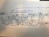
If I understand the schematic, Gray and Orange should read 28V AC, Red and Violet should read 36,4V AC.
(see attached picture).

It might be my lack of knowledge.....am I measuring the wrong way? Or should I check somewhere else?
IMG_2705.jpg
 
Register to hide this ad
What does measuring between black wires on the transformer and the wires that carry secondary voltage say?

You could also measure dc voltage at the CZ connectors disconnect them from the rest of the circuit first.
 
What does measuring between black wires on the transformer and the wires that carry secondary voltage say?

Only one black wire from transformer. All colored wires (red, grey, orange, violet) read only 0,033 V AC.

You could also measure dc voltage at the CZ connectors disconnect them from the rest of the circuit first.

CZ48: (DMM COM on pin 3 or 4)
between blue (pin 1) and black wire (pin 3 or 4): 2,9 mV DC (according to schedule this should be -46V DC)
between red (pin 2)and black wire (pin 3 or 4): 9,2 mV DC (according to schedule this should be +46V DC)

CZ46: (DMM COM on chassis)
pin 1: 0,011 V DC (according to schedule should be -37V DC)
pin 2: 0,011 V DC (according to schedule should be +37V DC)
pin 3: 0,011 V DC (schedule says I-V)
pin 4: 0,011 V DC (schedule says AC DET)
pin 5: 0,011 V DC (schedule says TRIG)
 
I will do that tonight and report back. My wife is ordening me to start cooking......

DMM COM on the black from transformer and measure AC voltage between secundary voltage wires I suppose.......
 
Hi Matjo,

Unplug the power lead from the wall and measure Ohms on the power lead pins with the power button on. This should measure the DC resistance of the primary winding. If it is up in the Meg Ohms then the Primary winding is open circuit.

Cheers.

GPS16
 
Hi Matjo,

Unplug the power lead from the wall and measure Ohms on the power lead pins with the power button on. This should measure the DC resistance of the primary winding. If it is up in the Meg Ohms then the Primary winding is open circuit.

Cheers.

GPS16

i will do that first, report It back here and will after that insolder the wires of the Transformator off the power supply board and measure the AC voltage. Correct?
 
Hi Matjo,

Unplug the power lead from the wall and measure Ohms on the power lead pins with the power button on. This should measure the DC resistance of the primary winding. If it is up in the Meg Ohms then the Primary winding is open circuit.

Cheers.

GPS16

Well.....first result: Measuring Ohms on power lead pins gives an overload as result (OL on display, no value was shown).

To have a better idea what we are talking about, it is a
Holmgren Toroidal Transformer, type TI-65381, custom manufactured for NAD.
no thermal fuse mentioned in schematic.
 
Disconnect transformer secondarys and try the voltage measurements again.

Dear Reddish75, desoldered the 5 colored wires coming from the transformer (not the main 230V blue and brown one) and measured AC voltage. All 5 wires (orange, black, gray, red and violet) started of with 25,2 Volt AC. but slowly the numbers were rising (on all wires), getting to 26,6 Volt AC.
I switched off the Amplifier and surprisingly the AC voltage is still there; moving around 24 V AC. I have measured with the DMM negative (COM) on the Chassis.

If I measure with Negative DMM connected to the black wire (which is supposed to be going to earth according to schedule) I measure everywhere a steady 0,04 V AC.

What I do not understand is:
1. How is it possible that I measure 26 Volts AC on the black wire (that should normally go from Transformer, via power board to ground) when negative DMM is on the chassis?
2. Why is there still AC voltage on the wires, even with Amplifier switched off?
3. If I measure AC voltage between brown & blue wire (coming from wall socket) it measures a 236V AC, which is good. If I measure between brown wire and chassis it measures 35,5V AC. Between blue wire and chassis 57,9 V AC. Blue wire goes straight in Transformer. Brown (35,5V AC?) goes via W1 & W2 red wires to the power switch on the front of Amplifier, after that to the Transformer.
If on/off switch is turned off, there is no continuity, if it is switched on, there is.

I haven't got a degree in electronics, not even close. But this does not sound logic to me at all.......
 
Last edited:
IMG_2713.jpg
This is the situation how I am measuring. Transformer still connected to power board through Blue and Brown wire. 5 other wires desoldered, all of them normally going to the fuses on the power board (4 fuses, 6.3A, 250V), only the black one should go to ground, according to schedule.
 
Last edited:
And what is the function of the 4n7 / 400 VAC Ceramic Capacitor (C435) on the little on/off switch board?
It feels as if the solder joints are not in the best condition anymore, I can move the Capacitor more than I think is normal. it is placed in paralel with the on/off switch-wiring, as shown on the schematic. It looks a bit hard to reach in order to resolver, want to do this only if it could make a difference.......


UPDATE: I had some spare time, so I took the capacitor out, checked if value was still ok (4500 pF in stead of 4700 pF as in schedule) and soldered back. Seems not to be the problem..........
 
Last edited:
Dear Reddish75, desoldered the 5 colored wires coming from the transformer (not the main 230V blue and brown one) and measured AC voltage. All 5 wires (orange, black, gray, red and violet) started of with 25,2 Volt AC. but slowly the numbers were rising (on all wires), getting to 26,6 Volt AC.
I switched off the Amplifier and surprisingly the AC voltage is still there; moving around 24 V AC. I have measured with the DMM negative (COM) on the Chassis.

If I measure with Negative DMM connected to the black wire (which is supposed to be going to earth according to schedule) I measure everywhere a steady 0,04 V AC.

What I do not understand is:
1. How is it possible that I measure 26 Volts AC on the black wire (that should normally go from Transformer, via power board to ground) when negative DMM is on the chassis?
2. Why is there still AC voltage on the wires, even with Amplifier switched off?
3. If I measure AC voltage between brown & blue wire (coming from wall socket) it measures a 236V AC, which is good. If I measure between brown wire and chassis it measures 35,5V AC. Between blue wire and chassis 57,9 V AC. Blue wire goes straight in Transformer. Brown (35,5V AC?) goes via W1 & W2 red wires to the power switch on the front of Amplifier, after that to the Transformer.
If on/off switch is turned off, there is no continuity, if it is switched on, there is.

I haven't got a degree in electronics, not even close. But this does not sound logic to me at all.......
The incoming AC is isolated from the chassis, you cannot measure it with black on the chassis. The only way to get an accurate measurement is directly across the primary winding. Meter on ac volts, plugged into mains, power switch on. Measure between P6 and P5. Are you reading your normal AC? What voltage do you have?
Can you post a picture of the front of your meter, so we can see what you are using, please.
 
Last edited:
OK, thanks!
Unplug from the wall, measure resistance at the same two points. That will tell you if the transformer primary is open, it should measure just a few ohms.
 
OK, thanks!
Unplug from the wall, measure resistance at the same two points. That will tell you if the transformer primary is open, it should measure just a few ohms.

Good evening Merlynski. First of all, great music choice (Pink Floyd rules!).
I did as instructed. Could not read a thing; DMM goes in o.L. mode, meaning somethings is wrong I suppose.......
I double checked by measuring some resistors on the power supply board as well; the all came out fine. So DMM should be OK.
 
Last edited:
What I also did: I have an other NAD here on my desk, a C370. I disconnected the CZ from the transformer to the main board and measured those values in AC Volt. They are pretty close to what the schematic of the C370 is saying, so do I have to come to the conclusion that the Transformer of the C320 (the one we are looking at now) is broken? can something like this be fixed or should I get a new transformer? Or am I totally thinking wrong here?
 
Looks like an open transformer winding, but just to be sure, did you measure resistance where the blue and brown wires from the transformer are connected to the circuit board? It looks like you are from the picture and the SM. Some transformers have a thermal fuse buried in the windings. If the transformer overheats the fuse opens. Usually this is unrepairable. Any known history or signs of over-heating of the transformer?
 
Looks like an open transformer winding, but just to be sure, did you measure resistance where the blue and brown wires from the transformer are connected to the circuit board? It looks like you are from the picture and the SM. Some transformers have a thermal fuse buried in the windings. If the transformer overheats the fuse opens. Usually this is unrepairable. Any known history or signs of over-heating of the transformer?

Thanks for the fast reply! Yes, I did measure on same spots as shown on picture; blue and brown wire going to the transformer.

On the schematic there is no mention of a thermal fuse, something I have seen on other NAD amplifiers. So I guess there is none.....

There is no know history of this amplifier. A friend of mine just dropped it in front of my door (Corona-time.......) asking me to check if I could fix it. Pretty bold to ask a guy that only has a little bit experience on old Sansui amplifiers.

I asked the guy if he had a spare transformer (or an other broken NAD from the same series). He will check it and if yes, I want to exchange them to see if we have located the problem of this Amp.
 
I notice it says Custom Made on the transformer. If you contact the transformer manufacturer you may be able to get an exact replacement directly from them. If they still have all the manufacturing data they should be able to reproduce it.
 
Back
Top Bottom