
• The move to the new server is done. There are some software and database maintenance updates in process. This has us passing the hat around to help out. We appreciate any donations. Seriously, even a dollar helps. The payment page may be found here - https://www.audiokarma.org/support.html

Power Supply / Smoothing Cap Question

CANT

Member
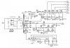
So, I'm not exactly sure how to ask this but I am curious about how values for this application are selected. I am currently working on or looking at a Sherwood S5000 II (7591) but general/generic answers are welcome and of interest because this unit has been modified. I bought this amp because it had supposedly been serviced by a reputable shop and I was tired of constantly working on my purchases... I wanted something guaranteed to function and this did/does but I couldn't help myself and opened the case, it's kind of a mess. All of the cans have been replaced by smaller lytics haphazardly jammed under the case with not all of the connection points being secured safely. I am looking into replacing some of what's going on with cans again to clean things up but unsure of what values to select.

1st, C3 (40/30/20) has been replace with 68/68/220. What is the point of or benefit to increasing the final section (phono) with a value so much higher than the original?

2nd, C4 (150/250/50) has been replaced with 270/1000/1000. Is this overkill or warranted for a bias supply/heater circuit?

I would normally trust in the expertise of the seller/shop as I am not that familiar with tube circuitry but I've found some glaring issues with the work done. Like the 4x 0.068uF coupling caps being replaced with 3x 0.1uF and 1x 0.01uF? The overall scope of the work appears to have prized speed/time over accuracy/quality which makes me suspect.

Thank you all for any assistance you can provide
 

Attachments
  • S5000 PS.JPG
    S5000 PS.JPG
    84.2 KB · Views: 26
Last edited:
Register to hide this ad
1) no idea. Doesn't seem to me it needs to be that big. You could make each of those double the original value without bothering anything but 10x seems excessive. Probably someone thought that bigger cap would make it quieter but honestly it should be plenty quiet already by the time it gets that far down the line.

2) also seems excessive. Maybe if you really felt compelled, bump the 150 a bit but otherwise I don't see that it needs to have huge capacitors in that circuit either.

I'd put the stock value coupling caps back in too. At an absolute minimum they should all be the same value. Originally they probably did use a 400v and a 250v cap but you can use the same voltage in both spots. My S-7000 and S-5500II at least did it that way.

I'm not hard sold on the notion that the original values of parts is the only possible way of getting it done, but changing things at random doesn't seem wise either. If I was going to bump anything in the power supply, it would be C1 and C2 from 150 to say 270. Those are the voltage doubler caps and having a bit more size there is usually good for regulation, but beyond a certain point its not going to do any good.

if you do replace the caps with cans, make sure you insulate C1. Its negative will be at 1/2 B+, around 240vdc.

When I re-capped my S-7000 I think I kept the caps to all close to the stock value, except I bumped the doubler caps to 220 or 270, don't remember which. Basically 50% over stock value. Coupling caps in that are actually all original still. I changed the power supply diodes, but only because I broke the leg on one while doing something else.
 
To add to gadget73's comments, be sure to check that the replacement caps are at least the voltage rating of the original or higher. Also, if making changes, ensure the existing electrolytic are discharged before working in there.
 
I'd say, the replacement caps were what the tech had lying around or easy access to purchasing. This happened a lot, in the 1970-80s "garage tech" era. :D
 
1) no idea. Doesn't seem to me it needs to be that big. You could make each of those double the original value without bothering anything but 10x seems excessive. Probably someone thought that bigger cap would make it quieter but honestly it should be plenty quiet already by the time it gets that far down the line.

2) also seems excessive. Maybe if you really felt compelled, bump the 150 a bit but otherwise I don't see that it needs to have huge capacitors in that circuit either.

I'd put the stock value coupling caps back in too. At an absolute minimum they should all be the same value. Originally they probably did use a 400v and a 250v cap but you can use the same voltage in both spots. My S-7000 and S-5500II at least did it that way.

I'm not hard sold on the notion that the original values of parts is the only possible way of getting it done, but changing things at random doesn't seem wise either. If I was going to bump anything in the power supply, it would be C1 and C2 from 150 to say 270. Those are the voltage doubler caps and having a bit more size there is usually good for regulation, but beyond a certain point its not going to do any good.

if you do replace the caps with cans, make sure you insulate C1. Its negative will be at 1/2 B+, around 240vdc.

When I re-capped my S-7000 I think I kept the caps to all close to the stock value, except I bumped the doubler caps to 220 or 270, don't remember which. Basically 50% over stock value. Coupling caps in that are actually all original still. I changed the power supply diodes, but only because I broke the leg on one while doing something else.

This all seems inline with what I was thinking... in my few previous go rounds with tube equipment I have replaced caps like the 40/30/20 with 40/40/40 just for ease but the 220uF was throwing me off. Same with the bias circuit too really? I would be more inclined to 3x 270's and call it a day? Maybe 2x 270's and a 47/56?

The coupling caps in this amp are spec'd at 600V which stinks because I have a slew of .1uF 400V's lying around but currently no 630V's. I didn't see the harm in the bump from .068uF but was disappointed that whomever did the work could be bothered to the same value for all 4.

I believe the doublers are actually 220 or 270 but it is a bit hard to tell because they glued (silicone I believe) down and I don't want to rip them up just to check so I am going off of the spec sheet sizing and the scope of the rest of the work done. Oh and all of the voltage ratings appear to be correct per cap application... honestly, caps are all good quality Nichicon, Rubycon and such... the work is just a bit sloppy.
 
I won't be too harsh, some of my early work is not exactly anything I'm proud of.

I read this as "I wouldn't be too harsh" so if I am incorrect I apologize but I wanted to say that I am trying not to be... My critique is mostly informed by the reputation of the shop that supposedly did the work (sellers word) and what I paid for it given the service I was told it had. And the coupling cap issue was an example of but not by any means the only issue I've found in the work done.

I would like to thank everyone for their assistance with this question.
 
That wasn't really what I was aiming at, I was just going to say I won't say too much bad about things being messy just because I've probably done worse before I knew better.

That said, there is a big difference between one of my at-home cobble jobs on some piece of junk for myself and a paid-for "pro" job. I would expect better on something that cost actual money to have done.
 
Back
Top Bottom