
• The move to the new server is done. There are some software and database maintenance updates in process. This has us passing the hat around to help out. We appreciate any donations. Seriously, even a dollar helps. The payment page may be found here - https://www.audiokarma.org/support.html

Pre-amp power supply needs a sanity check please!

thorpej

AK Subscriber
Subscriber
So, I'm about to dive into building a low-gain 6AS7 / 6080-based stereo pre-amp, and was talking to a buddy about it and he expressed interest in it, but he wants tone controls and a phono stage.

"Ok, sure!", I said.

I need ~160V for the 6AS7 gain/output stage (that will be loaded with a CCS), and ~250V for the phono and tone stages (for a total of 4 12AX7s).

I had planned to use the AnTek AS-05T120 toroidal power transformer (and, in fact, I had already ordered a pair of them before my friend convinced me to build one with the extra stuff). Luckily, this transformer has enough oomph in the heater windings to handle all of the tubes I need to light up (2x 2A 6.3V windings, which will be fed in parallel to a regulated DC heater supply). And, as luck would have it, this transformer also has a 100V tap on the secondary winding.

So, my thought was to use a full-wave bridge rectifier on the entire winding for the 160V supply, and a voltage doubler on the 100V tap to get the 250V supply. I think this will work, but I wanted to run the proposed circuit by the experts because the 100V output is really a tap on the secondary, and not a separate winding.
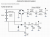
Screen Shot 2018-08-09 at 11.04.13 AM.png
 
Register to hide this ad
This looks like a recipe for disaster to me. You might try a half-wave doubler instead --- the input coupling cap should keep you out of trouble.
 
This looks like a recipe for disaster to me. You might try a half-wave doubler instead --- the input coupling cap should keep you out of trouble.

This is why I ask questions :-)

Now if I could just figure out how to correctly model the multi-tap transformer in LTSpice, I wouldn't have to ask such silly questions in public...
 
Yes, but I only need one of them. They're the voltage gain *and* the output drive of the pre-amp, one triode per channel (their output impedance even with a CCS load is only ~280 ohms).
OK,, I only mentioned it cause I tried to use a 10A FT for 2 x 811s (4A each),, and voltage dropped below 6V after an hour or so... ended up using a 10A FT for each 811... You are at 3.7A w/4A Tx,,,
Try it before you cut holes,,, hate to see you need another Tx after its built!!!
 
This looks like a recipe for disaster to me. You might try a half-wave doubler instead --- the input coupling cap should keep you out of trouble.

So, I simulated the half-wave doubler circuit in isolation, and amusingly it performed better on its own than the bridge doubler did ¯\_(ツ)_/¯. But when I was updating my schematic where the two are combined, a problem became obvious: In the half-wave configuration, the bottom end of the PT winding is ground-referenced (which how the voltage gets doubled on the cycle that's positive on the lead with the series cap). I obviously can't connect it that way if I'm using a bridge rectifier across the entire winding for the 160V supply.

So, other suggestions are welcome. It may be that I have to bite the bullet and use an additional transformer for the 250V supply. The Triad F3-120 would be more than adequate for the half-wave doubler supply, and the way that series of transformers is constructed, would probably be OK to mount under the chassis without creating a noise problem (I've done this before in a power amplifier, using this type of transformer for a bias supply, and electrical noise from the transformer wasn't a problem).
 
You should be able to simulate the power transformer secondary as ideal AC voltage sources. In this case a 100V AC secondary in series with a 20V AC secondary. For the feasibility type study you're looking for, that should be enough.
 
This is why I ask questions :)

Now if I could just figure out how to correctly model the multi-tap transformer in LTSpice, I wouldn't have to ask such silly questions in public...
This transformer is not really a "multi-tap transformer", I see it as a dual output isolation trans. with either a 120v tap for North America use or a 100v. used for (1/2) of Japan. Buy a proper transformer and forget the doubler. Plus why use a 6AS7? Its gain is only 2 !
Talk about low gain ! I used one for a headphone amp. but it needed low output impedance.
 
This transformer is not really a "multi-tap transformer", I see it as a dual output isolation trans. with either a 120v tap for North America use or a 100v. used for (1/2) of Japan. Buy a proper transformer and forget the doubler. Plus why use a 6AS7? Its gain is only 2 !
Talk about low gain ! I used one for a headphone amp. but it needed low output impedance.

If it's what you say it is, why does it have dual 6.3Vac secondary windings in addition to the 120Vac secondary-with-100V-tap? They clearly market it as a power transformer for tube electronics. I've used several AnTek transformer models before, and they're not hack jobs. This transformer is actually ideal for the operating point I want to run the 6AS7 at.

As for why 6AS7 -- because I want to build a low-gain pre-amp, and was inspired to use this tube based on a previous thread here on AK started by @kward as well at Pete Millett's low-gain pre-amp that also used 6AS7 (my topology is really similar to Pete's, except I'm using IXYS 10M45s rather than EL34s as the constant current sources). None of the amplifiers I have are difficult to drive to full power at all.
 
You should be able to simulate the power transformer secondary as ideal AC voltage sources. In this case a 100V AC secondary in series with a 20V AC secondary. For the feasibility type study you're looking for, that should be enough.

Yah, the same thing occurred to me. I'll fiddle with it some more tonight.
 
and was inspired to use this tube based on a previous thread here on AK started by @kward as well at Pete Millett's low-gain pre-amp that also used 6AS7
and it's still on my list to build, just pushed down the stack somewhat given the life events that have needed to take priority. I'll be watching your thread here with interest...
 
Sorry, i forgot about the 6.3v windings. What gain are you looking for?

Approx 2. Hence my choice of tube. (Before I was inspired to use a power triode for the application, I was going to build a standard gain-stage-with-cathode-follower-and-NFB pre-amp with a gain of approx 2.)
 
That's just 6 dB. There won't be much action on the volume control. Is that the goal? Leaving it near full to get decent volume? ( This design is so unusual)

Most of my power amps can be driven to full power with just consumer line sources ... e.g. a CD player without a built-in attenuator on its output would play the CD at full volume (which would definitely result in the neighbors calling the cops). But a few of my amps can't *quite* be driven to full power by just line sources, where a voltage gain of 2 would be more than enough get it there. (Even a Dynaco ST-70 can be driven to full power by applying 2x voltage gain to today's consumer line level sources.)
 
Back
Top Bottom