• The move to the new server is done. There are some software and database maintenance updates in process. This has us passing the hat around to help out. We appreciate any donations. Seriously, even a dollar helps. The payment page may be found here - https://www.audiokarma.org/support.html

Primare pre30 doesn't turn on

depaj

Active Member
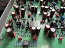
A week ago I got this Primare PRE30 from a friend. I'm used to working on older gear so I didn't promise anything but said I would try. The unit doesn't turn on (not even the standby indicator). The power supply delivers all the right voltages and all the opamps seem fin (+/- rails are there and only a 1 or 2 mV max on the outputs). Does anyone know of a common problem somewhere that might cause this and if the microcontroller is faulty, is it possible to reprogram one (I don't have the necessary matériel but someone might). They seem still available.

Thank you :)
 
Register to hide this ad
Hi!
Thanks but I got those now. I got a contact with a french dealership for Primare and they might be able to help me, I'm waiting on an answer from them tomorrow.
 
Nice, hope they can help you.
Wondering if you might know how to adjust the 4 multi-turn PR1,2,3 and 4? Or if you may ask them... Anyway you'll probably also need to know how to adjust them when you get the initial problem fixed ...
Thank You
Good luck
 
I have no idea, might be an offset adjustment for each stage but not sure. Couldn't find any info on it, I will try and ask them.
 
Hi!

Yes I did, they were very helpful but unfortunately sent me the wrong micro controller chip. Now I just have to hope this was just a mistake and they have the right one in stock.
 
Back again,

I got a new control chip, programmed by Primare themselves, the PRE30 now turns on but all the lights are on, I have just one dash on the display and none of the commands work so still no sound.
I'm still looking for any defective chips but if anyone has an idea as to where to look I would be very grateful.
 
Hi there
This vary, vary old, nevertheless did you successfully solve this issue?
Did you've any chance to query or find out how to adjust bias?
 
Hi!

This was indeed a very long time ago. Turns out back then I had some time and wrote everything down. I started by replacing the micro controller which gave me a nice christmass tree because all the leds lit up but none of the commands were working. The micro controller was sending but didn't receive anything back nor did the information get where it needed to go. This was because two of the other chips were bad, I ended up replacing all four SOIC-16 chips on that board. At that time I had regained all functions but still no sound because the relays weren't engaging. So I also replaced U2, U3 and U13 that command the relays and finally got sound. I did have some terrible noises when switching between inputs which was caused by all three ground resistors to be open (the one right under the top left mounting screw on the main board and the two located just above U3 and U13, that is looking down from over the amp with the faceplate facing you). If I remember correctly the variable resistors are for offset not bias but I can be wrong.
I can send you the schematics if you need them.
Hope this helps !
 
Hi!

This was indeed a very long time ago. Turns out back then I had some time and wrote everything down. I started by replacing the micro controller which gave me a nice christmass tree because all the leds lit up but none of the commands were working. The micro controller was sending but didn't receive anything back nor did the information get where it needed to go. This was because two of the other chips were bad, I ended up replacing all four SOIC-16 chips on that board. At that time I had regained all functions but still no sound because the relays weren't engaging. So I also replaced U2, U3 and U13 that command the relays and finally got sound. I did have some terrible noises when switching between inputs which was caused by all three ground resistors to be open (the one right under the top left mounting screw on the main board and the two located just above U3 and U13, that is looking down from over the amp with the faceplate facing you). If I remember correctly the variable resistors are for offset not bias but I can be wrong.
I can send you the schematics if you need them.
Hope this helps !
Hi,
Thank You for your reply.
Glade to know you have succed on bring back to live this good pre-amp.
I've the service manual but I don't know enough electronics to look at it and find where to connect multimeter tips for RP1 to RP4 adjust result, needer which values should I'm get. Can't find it nowhere and Primare support doesn´t tell me claiming that's for my own safe ... If I can't find it, it looks like I'll have to send them my diploma.
For this yours late post I acn tell that you know mutch more then me, and I hope I'm not ask to mutch, but would you please take a look and give your opinion?
I've attached my service manual so you can tell if is the same you have, and also pictures showing some board tips, they must be there for some reason ...
Thank You in advance
Regards
 

Attachments

  • PRE30 Service Manual.pdf
    PRE30 Service Manual.pdf
    675.1 KB · Views: 6
  • IMG_3274.jpg
    IMG_3274.jpg
    102.9 KB · Views: 4
  • IMG_3275.jpg
    IMG_3275.jpg
    146.7 KB · Views: 4
There's a good chance that these don't need to be adjusted. From looking at the service manual you have four stages, 2 inverted and 2 non-inverted for the balanced outputs. Each pot adjust offset of one stage. You can measure between ground pin and the + an - pins of each xlr output and aim for as close to 0VDC as you can get. I would also mark the actual setting precisely before touching anything and again, measure at the outputs before touching the pots, if it is within a few mV from 0VDC I wouldn't worry. Is there anything actually wrong with it ? If there isn't I wouldn't touch it.
 
There's a good chance that these don't need to be adjusted. From looking at the service manual you have four stages, 2 inverted and 2 non-inverted for the balanced outputs. Each pot adjust offset of one stage. You can measure between ground pin and the + an - pins of each xlr output and aim for as close to 0VDC as you can get. I would also mark the actual setting precisely before touching anything and again, measure at the outputs before touching the pots, if it is within a few mV from 0VDC I wouldn't worry. Is there anything actually wrong with it ? If there isn't I wouldn't touch it.
Hi,
Thank you for spend some time looking to the service manual and elaborate your opinion.
Yes, all you wrote make perfect sence for me. Just that board pins/tips on the pictures I've upload make me less and less confindent ... still wandering wich use they have ...
No there isn't anything wrong with it, some times the rotary on/stand-by need more then a change to switch to or from stand-by, thats all.
But, just because I've to repair the wells on my Audio/TV furniture and take all equipment from it, have decided vacuum all inside and check all adjusts on all, and some spray contact cleaner on that rotary 12 way switch.
And once again you are write all the xlr (pin 2 and 3) do have arround 5mv but one off then was arround 10mv and I should have done any adjust, but ... I couldn't resist.
Now the worst is max 2mv and 2 of then 0v.
Can't ear any difference, just the on/stand-by is ok now, but got this good feeling of work well done :)
Thank you, all the best to you
 
I think the pins probably connect to the outputs of the stages as well and are there to measure offset but they aren't indicated on the schematic so I figured it would be safer to just connect to the XLR. 2mV is great I would leave it there and enjoy.
Happy to help
 
Back
Top Bottom