


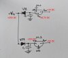
Ok here's a horrible freehand sketch of the power supply into the voltage regulators.
Note1: NL1 is the 78L15 positive voltage regulator and NL2 is the 79L15 negative voltage regulator.
Note2: Ground is to the power supply plug (the outer ring of metal), not to the chassis.
It appears that VD1 is supposed to output negative voltage into NL2. I don't totally understand how a +DC supply into the cathode can result in negative voltage on the other side (shouldn't it be AC?) - but what do I know?
This circuit appears to be extremely simple. Looking at it, what else than VD1 being bad could be preventing -25V from getting to NL2? VD1 does measure OK with my multimeter ...
C1 and C2 are both new 470uF / 25V capacitors.
Note1: NL1 is the 78L15 positive voltage regulator and NL2 is the 79L15 negative voltage regulator.
Note2: Ground is to the power supply plug (the outer ring of metal), not to the chassis.
It appears that VD1 is supposed to output negative voltage into NL2. I don't totally understand how a +DC supply into the cathode can result in negative voltage on the other side (shouldn't it be AC?) - but what do I know?
This circuit appears to be extremely simple. Looking at it, what else than VD1 being bad could be preventing -25V from getting to NL2? VD1 does measure OK with my multimeter ...
C1 and C2 are both new 470uF / 25V capacitors.
Last edited:
 So I guess now I have to find a 16V AC power supply ...
