Super Noob
Super Member
Much easier... amp boards unplug.Great rebuild thread. Are you saying restoring your 2275 was easier than the 2270?
https://audiokarma.org/forums/index.php?threads/project-marantz-2275.866240/


Much easier... amp boards unplug.Great rebuild thread. Are you saying restoring your 2275 was easier than the 2270?


Power Supply Board (P-800)
C801 - Original 470uF 63v / Now 1000uF 63v (UPW1J102MHD)
C802 - Original 330uF v / Now 680uF 63v (UPW1J681MHD6)
C803 - Original 470uF 16v / Now 470uF 16v (UPW1J102MHD)
C804 - Original 330uF v / Now 680uF 63v (UPW1J681MHD6)
C805 - Original 3.3uF 35v / Now 10uF 50v (UKT1H100MDD)
C806 - Original 10uF 50v / Now 22uF 50v (UKA1H220MDD)
C807 - Original 220uF 10v / Now 220uF 35v (UKA1V221MPD)
C810 - Original 47uF 16v / Now 47uF 35v (UK1V470MDD)
H801 – Original S1B-01-02 / Now UF4005
H802 – Original S1B-01-02 / Now UF4005
H803 – Original 2SD315 / Now MJE15032G (T-66 to TO-220)
H804 – Original BZ-140 / Now 1N4744A (OnSemi)
H806 – Original 2SC734 / Now Now KSC2383YTA
H807 – Original WZ-071 / Now N4737A (OnSemi)
H808 – Original SC945 / Now KSC2383YTA
H809 – Original 2SC1213A / Now KSC2383YTA
H810 – Original 2SC1213A / Now KSC2383YTA
H811 – Original S1B-01-02 / Now UF4005
H812 – Original S1B-01-02 / Now UF4005
H813 – Original S1B-01-02 / Now UF4005


Nice catch! This is the post by Leestereo that I have always used to orient my flyback diodes. This is on a 2270.Regarding the flyback diode arrangement...I connected as described in post #3 and thank goodness I was on dbt when I powered up. I admittedly did not verify these connections, but strictly went on the information as stated. Lesson learned.
Post #18 in the thread linked below gives a little more information on this modification.
https://audiokarma.org/forums/index...oration-and-upgrade-of-a-marantz-2270.793805/
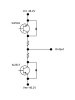
Per the attached drawing the diodes should be arranged as follows:
SJ2517: Collector (Cathode) : Emitter (Anode)
SJ2518: Collector (Anode) : Emitter (Cathode)
In my amp:
SJ517 Collector => J760 => Cathode
SJ517 Emitter => J761 => Anode
SJ2518 Collector => J754 => Anode
SJ2518 Emitter => J753 => Cathode
I'm not sure if this is simply a good old fashioned cathode/anode mixup or what, but a word of caution.
Thank you.