

SebastianH
Member
Hey guys,
I have been working on a quick project: A (drop-in) solid state relay replacement for relays with the footprint of Omron's MY2 (and similar) used as speaker protection relays.
Today I'm too lazy to write a long post, so Q&A it is:
Why?
Because I don't think I have seen a compact (drop-in) replacement yet and it was fun to design and build.
And I think - have not tested - it will switch off (reasonable) fault currents without destructing itself. From the relay's perspective it's no longer required to mute the signal before turning on/off the amp.
How does it look like?
Here is an old Omron 4PST relay next to my Solid State Relay (DPST):

Is it a drop-in replacement for something like the Omron MY2?
It depends on the application (i. e. electrical requirements, thermal conditions), MOSFETs used etc. This was meant as a speaker protection relay first - DPST. It's absolutely required to check whether it's a suitable replacement for the application.
What gate driver and MOSFETs does it use?
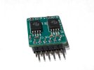
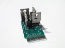
2x Texas Instruments TPSI3052 Isolated Switch Driver; Infineon IPP026N10NF2S (100V, 2.6mOhm, 184A, 430mJ). There are a whole bunch of nice MOSFET that would be good candidates, e. g. some with a higher voltage rating.
What's the on resistance? How much current can it handle?
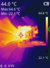
The on-resistance of the relay depends on its temperature. I'd expect something between 6 and 10 mOhm under load. Measured about 7mOhms under load without the pins. The current handling capability depends on the cooling. At room temp (20°C) something like 10A should be possible; have only tested one pole at 10A. After 15min the case temperature was about 65°C. 10A continuous current is waaay more than I ever need.
What voltage may I apply to the relay?
The relay uses a bridge rectifier so that the polarity of the control signal does not matter.

In its two-wire mode the TPSI3052 has an absolut maximum rating of 60V; with the bridge rectifier installed it requires something like 6-6.5V to turn on. So it could be used as a 12V, 24V and 48V relay. But again: The drive circuit matters... In its current configuration it needs something like 5mA steady state if I remember correctly.
Does it actually work? How do I know whether the amplifier is in protection if there is no audible click?
Yes, it does. Have a guess which amplifier this is The relay has 2 LEDs (one for each pole) that indicates whether the respective TPSI3052 transfers power to the gate driver side. Under normal operation conditions this is somewhat equivalent to: the gates are either already or will soon be driven high. (There is a delay between "relay powered" and "gate driven high" - the gate charge (or actually multiple times the gate charge) has to be accumulated in capacitors to quickly turn the MOSFETs on.)
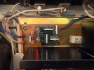
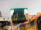
Some amps have a protection LED, others don't. This amp doesn't, so I added a circuit from its big brother that lets the power LED blink when in protect:
Are there more measurements?
I have a couple more measurements and additional information on my website (https://sebastianharnisch.de).
Happy to answer questions/get some feedback
Sebastian
I have been working on a quick project: A (drop-in) solid state relay replacement for relays with the footprint of Omron's MY2 (and similar) used as speaker protection relays.
Today I'm too lazy to write a long post, so Q&A it is:
Why?
Because I don't think I have seen a compact (drop-in) replacement yet and it was fun to design and build.
And I think - have not tested - it will switch off (reasonable) fault currents without destructing itself. From the relay's perspective it's no longer required to mute the signal before turning on/off the amp.
How does it look like?
Here is an old Omron 4PST relay next to my Solid State Relay (DPST):
Is it a drop-in replacement for something like the Omron MY2?
It depends on the application (i. e. electrical requirements, thermal conditions), MOSFETs used etc. This was meant as a speaker protection relay first - DPST. It's absolutely required to check whether it's a suitable replacement for the application.
What gate driver and MOSFETs does it use?
2x Texas Instruments TPSI3052 Isolated Switch Driver; Infineon IPP026N10NF2S (100V, 2.6mOhm, 184A, 430mJ). There are a whole bunch of nice MOSFET that would be good candidates, e. g. some with a higher voltage rating.
What's the on resistance? How much current can it handle?
The on-resistance of the relay depends on its temperature. I'd expect something between 6 and 10 mOhm under load. Measured about 7mOhms under load without the pins. The current handling capability depends on the cooling. At room temp (20°C) something like 10A should be possible; have only tested one pole at 10A. After 15min the case temperature was about 65°C. 10A continuous current is waaay more than I ever need.
What voltage may I apply to the relay?
The relay uses a bridge rectifier so that the polarity of the control signal does not matter.
In its two-wire mode the TPSI3052 has an absolut maximum rating of 60V; with the bridge rectifier installed it requires something like 6-6.5V to turn on. So it could be used as a 12V, 24V and 48V relay. But again: The drive circuit matters... In its current configuration it needs something like 5mA steady state if I remember correctly.
Does it actually work? How do I know whether the amplifier is in protection if there is no audible click?
Yes, it does. Have a guess which amplifier this is
The relay has 2 LEDs (one for each pole) that indicates whether the respective TPSI3052 transfers power to the gate driver side. Under normal operation conditions this is somewhat equivalent to: the gates are either already or will soon be driven high. (There is a delay between "relay powered" and "gate driven high" - the gate charge (or actually multiple times the gate charge) has to be accumulated in capacitors to quickly turn the MOSFETs on.)Some amps have a protection LED, others don't. This amp doesn't, so I added a circuit from its big brother that lets the power LED blink when in protect:
Are there more measurements?
I have a couple more measurements and additional information on my website (https://sebastianharnisch.de).
Happy to answer questions/get some feedback
Sebastian
Last edited: