• The move to the new server is done. There are some software and database maintenance updates in process. This has us passing the hat around to help out. We appreciate any donations. Seriously, even a dollar helps. The payment page may be found here - https://www.audiokarma.org/support.html

Proton D-1200 scorch-o-rama repair possible?

Dan D.

Active Member
Recently procured my holy grail amp knowing it was a basket case...impacted with dust, dirt, and who knows what else? (Who would DO such a thing to one of these?) I knew it wasn't fully operational, but could not pass it up in the unlikely event I could actually get it to cough to life. What I found was some real estate on the bottom of the pcb with fried/melted traces. I'm not expecting to restore the beast to it's original unmolested glory, just want to get it working and reliable. This will be a keeper, so it won't bother me to have visible repair work inside. If the bubbled traces check ok for continuity, should that be good enough? Or implant wires in place of the traces? I haven't done any solder trace rebuilding, so that's probably out, unless it's easier than I think. I'm open to any suggestions. This will be attempted knowing that whatever fried it is still in need of replacing. Let's have it, gang. What do you think? - Dan

d1200 scorch.jpg P1220002.JPG
 
Register to hide this ad
Well,just to get you started,methinks you're gonna need one of these:
(seriously though,with a little practice,trace repair is a lot easier than you may think)

CR-Magazine-Inlinehero-pressure-washer-qanda-May-2019-0419
 
I considered dipping the whole board in the ultrasonic cleaner at the shop. Less relays and anything else that wouldn't like water. It would chew away at the enamel coating on any windings though. Plus there's a bit more to removing the board than I'm comfortable with. Simple green, a small brush and air nozzle it shall be. One section at a time.
 
Looks like you have quite the project in front of you. Good luck. That amp is on my want list also. I have a thing for meters....
 
Are you certain that the bubbles are not simply from a conformal coating reacting to atmospheric contaminants, or a spilled substance?
 
Agreed above. bubbling? There are self stick trace repair sheets and trace material online. I wonder if any pcb board views are avail.like in service manuals? To get new board(s) made from services online. I think the can image a stripped board, too.
 
Looks like quite the job!
I’d post a WTB on Bartertown to see if someone has a parts unit in their hoard. That would save you a lot of work.

If that doesn’t work out and the bubbled coating is due to corroded traces you will have quite a bit of repair to do but it doesn’t look like very tight, space wise.
 
If those traces are burnt, there is more than likely much deeper issues going on. Something is drawing way to much current. First thing you want to find is a set of schematics, either for yourself or your tech.

BillWojo
 
I would first do continuity checks on all the traces that are bubbled. The worst shown with the peeled lacquer you're going to have to clean and make sure there's no touching of the traces (looks like there should be two there). For long term reliability, just do some point to point wiring since there's not too many to do.

Not quite as extensive as what you'll need to do, but you get the idea...

15206208881_0554d3b574_o.jpg
 
Last edited:
Recently got in some practice resurrecting another Proton, a receiver with fried tidbits and traces gouged out by a previous owner. (I refuse to even guess wtf they were thinking.) I did the point to point suggestion and it worked great. I think I'll do the same here along with replacing everything possible in the fried area. I'm not worried about cosmetics or originality now because I plan to keep this one for a long time. When I get back into it I'll post updates. Thanks for all the responses. - Dan
 
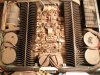
IT'S ALIVE. And thumping away nicely in the livingroom. After several lunchtime sessions at work with brushes, q-tips, Simple Green and an air compressor, it started to shine inside again. Then the parts trickled in for a few weeks and put some miles on the soldering gun. I forgot how difficult it is to get a respectable photo of black shiny things without all kinds of reflections, so there isn't a good shot of the exterior. I'll give it an easy 8 of 10 though. Photo was taken with a few pieces still missing, but the bath made a huge difference. Point to point trace repair isn't pretty, but it did work. The left channel has most of the new bits and runs a lot cooler than the right, but sounds pretty even at first listen. Eventually I'll replace the same components on the right, just to even things out. Led's all around and looks great. I know one thing, the new Abbey Road set sounds INCREDIBLE. Ohhhhh myyyyy....
Thanks to all for the tips and advice! - Dan0513201323_Burst01.jpg
 
I had three of those amps - two of them were the bridgable ones. The D1200 is the most powerful consumer power amplifier ever marketed and sold. Period.
 
I had three of those amps - two of them were the bridgable ones. The D1200 is the most powerful consumer power amplifier ever marketed and sold. Period.
Considering the small room it's in, and the close proximity to my neighbor, I don't see turning this beast up past the halfway mark. Having a bridgeable model would be even more overkill. As it is now, I can rattle the pots and pans in the kitchen enough to be an annoyance. Maybe acoustic foam in the cabinets?
And that's a nice Cutlass. Yours?
 
Considering the small room it's in, and the close proximity to my neighbor, I don't see turning this beast up past the halfway mark. Having a bridgeable model would be even more overkill. As it is now, I can rattle the pots and pans in the kitchen enough to be an annoyance. Maybe acoustic foam in the cabinets?
And that's a nice Cutlass. Yours?
Yessir.
 

Attachments

  • F660D9C6-7670-46BD-B387-2DF04BFC7E98.jpeg
    F660D9C6-7670-46BD-B387-2DF04BFC7E98.jpeg
    152.4 KB · Views: 16
I would seriously consider replacing the two lavender Matsushita caps near the output RCAs. I've found them to have a high failure rate and cause all sorts of problems. They look to be in the audio path (guessing) so depending on their value (uF/V) I'd replace them with (in order of preference) Film, Nichicon UKL (Low Leakage series), Nichicon UES or a high quality Audio Cap. For "dial a sound" perhaps socket pins could be temporarily soldered in the board and then try different "flavors" of cap to find what sounds best to you. If you choose a cap like KZ, the leads may not fit into sockets though.
 
There's a similar colored, similar vintage 2-1/2 ton Lincoln compressing the concrete in the garage here, less the air compressor poking through the hood. Long live 70's iron.:beatnik:

I would seriously consider replacing the two lavender Matsushita caps near the output RCAs. I've found them to have a high failure rate and cause all sorts of problems. They look to be in the audio path (guessing) so depending on their value (uF/V) I'd replace them with (in order of preference) Film, Nichicon UKL (Low Leakage series), Nichicon UES or a high quality Audio Cap. For "dial a sound" perhaps socket pins could be temporarily soldered in the board and then try different "flavors" of cap to find what sounds best to you. If you choose a cap like KZ, the leads may not fit into sockets though.
I wondered who made the pretty colored, bubbled and fried caps I took out. Thanks, I'll remember this the next time I get into it.
 
Back
Top Bottom