sae-7125
Super Member
if you are not familiar with the brand and/or type of device:
https://www.soundstagenetwork.com/revequip/psaudio_p300.htm
it would appear that the p300 went through some bandaid design rev's after certain serial number thresholds. this particular unit is less than #1000. newer versions show pictures of a cooling fan system vs the eventual doorstop sealed oven staring me in the face. initial thermal design was apparently beyond poor, more like catastrophic. although the grand canyon was not created in a day, so a predictable failure mode will take some time to manifest (outside of warranty).
i wonder what happens when the electrolytics large or small cook sufficiently to cause the outputs to fail? and when the outputs dump all that rail-to-rail dc into whatever is plugged into this thousand dollar device? only time will tell.
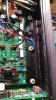
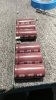
this particular unit failed in the field and lived a few years on a shelf. there is a nice youtube video where someone in the uk repaired a unit with blown outputs, it had a cooling fan. one thing he noted was the odd use of kapton tape between the power transistors and the metal heat sink instead of thermal grease and mica voltage isolation (think about it, why its a bad idea). also note the rails of 1800uf 160v electrolytics mounted on top of the output transistor compression bar (seriously?). newer versions show the caps mounted above the main board and in front of the after-thought cooling fan.
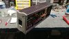 bottom panel only access.
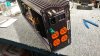 some units had tan/white receptacles.
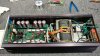 the electron arena (freq gen board/card/module removed prior to photo shoot).
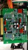
frequency generator module (note the gold plated edge connection). main board socket looks like tin or a dissimilar metal, gee i wonder why that might be a problem (386/486 30-pin ram modules anyone).
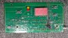 display board plus a touch of carbon pcb cancer (prior to cleaning the pcb), bulb is 30v 2watt.
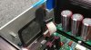 carbon on face plate, whatever failed must have blown through the pcb.
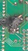
after cleaning the crater, more than traces missing.
there are 2 mps 8599 pnp transistors in parallel for the bulb circuit, both measure 100-200 ohms between pins 1&2 and 20-40 ohms between 2&3 (if i remember correctly).
https://www.mouser.com/datasheet/2/308/1/MPS8099_D-2316102.pdf
the pnp's are rated for 150c and ta= 625mw tc= 1500mw (derate above 25c/77f). if this circuit is driving a bulb load of 2 watts (low precision device/load) something seems potentially problematic (hello math). i had to look up ta vs tc for my own edification.
https://forum.digikey.com/t/ta-vs-tc-vs-tj-ratings/762
its interesting how the display board utilized led tech for the segmented digits and green yellow red indicators but used a 2w space heater for the logo illumination. just because old mcintosh gear used bulbs doesn't mean its a good idea (melted red film comes to mind).
regardless of the design flaws and mediocre build quality (iec plug/switch module + silicone caulk = structural failure when removing mains cord) the device has some potential for dialing in ac mains voltage and frequency. this tar+feathers diagnostic should not be confused with a retort of an irate owner who might pontificate between "avoid ps audio" and the ever popular "ps audio sucks".
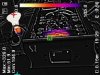
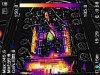
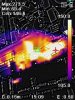
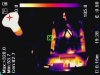
i don't own this stuff, just trying to put out the fires and give the local landfill less to eat, that thing needs to go on a diet (the landfill). i should have some baseline thermal photos soon, initial shots show the freq gen card is thermally aggressive and no heat sinks used. no "8 hours at idle" thermal shots yet, seems like this little monster gets warm even when nothing is plugged into it.
https://www.soundstagenetwork.com/revequip/psaudio_p300.htm
it would appear that the p300 went through some bandaid design rev's after certain serial number thresholds. this particular unit is less than #1000. newer versions show pictures of a cooling fan system vs the eventual doorstop sealed oven staring me in the face. initial thermal design was apparently beyond poor, more like catastrophic. although the grand canyon was not created in a day, so a predictable failure mode will take some time to manifest (outside of warranty).
i wonder what happens when the electrolytics large or small cook sufficiently to cause the outputs to fail? and when the outputs dump all that rail-to-rail dc into whatever is plugged into this thousand dollar device? only time will tell.
this particular unit failed in the field and lived a few years on a shelf. there is a nice youtube video where someone in the uk repaired a unit with blown outputs, it had a cooling fan. one thing he noted was the odd use of kapton tape between the power transistors and the metal heat sink instead of thermal grease and mica voltage isolation (think about it, why its a bad idea). also note the rails of 1800uf 160v electrolytics mounted on top of the output transistor compression bar (seriously?). newer versions show the caps mounted above the main board and in front of the after-thought cooling fan.
bottom panel only access. some units had tan/white receptacles.the electron arena (freq gen board/card/module removed prior to photo shoot). frequency generator module (note the gold plated edge connection). main board socket looks like tin or a dissimilar metal, gee i wonder why that might be a problem (386/486 30-pin ram modules anyone).
display board plus a touch of carbon pcb cancer (prior to cleaning the pcb), bulb is 30v 2watt.carbon on face plate, whatever failed must have blown through the pcb. after cleaning the crater, more than traces missing.
there are 2 mps 8599 pnp transistors in parallel for the bulb circuit, both measure 100-200 ohms between pins 1&2 and 20-40 ohms between 2&3 (if i remember correctly).
https://www.mouser.com/datasheet/2/308/1/MPS8099_D-2316102.pdf
the pnp's are rated for 150c and ta= 625mw tc= 1500mw (derate above 25c/77f). if this circuit is driving a bulb load of 2 watts (low precision device/load) something seems potentially problematic (hello math). i had to look up ta vs tc for my own edification.
https://forum.digikey.com/t/ta-vs-tc-vs-tj-ratings/762
its interesting how the display board utilized led tech for the segmented digits and green yellow red indicators but used a 2w space heater for the logo illumination. just because old mcintosh gear used bulbs doesn't mean its a good idea (melted red film comes to mind).
regardless of the design flaws and mediocre build quality (iec plug/switch module + silicone caulk = structural failure when removing mains cord) the device has some potential for dialing in ac mains voltage and frequency. this tar+feathers diagnostic should not be confused with a retort of an irate owner who might pontificate between "avoid ps audio" and the ever popular "ps audio sucks".
i don't own this stuff, just trying to put out the fires and give the local landfill less to eat, that thing needs to go on a diet (the landfill). i should have some baseline thermal photos soon, initial shots show the freq gen card is thermally aggressive and no heat sinks used. no "8 hours at idle" thermal shots yet, seems like this little monster gets warm even when nothing is plugged into it.