• The move to the new server is done. There are some software and database maintenance updates in process. This has us passing the hat around to help out. We appreciate any donations. Seriously, even a dollar helps. The payment page may be found here - https://www.audiokarma.org/support.html

PS Audio Reference advice

Ilikerotels

AK Subscriber
Subscriber
Good Afternoon,

I received this particular model PS Audio reference after someone had plugged it into a 240V outlet when it was set for it's native 110V ( I'm in the UK )

Upon replacing the 0.5A 250V internal fuse the new owner told me it kept blowing the fuse and could i take a look.

This particular mode uses 3 transformers for the DAC, front display section and main power to the board. I removed all 3 and tested them and there was no shorts on either primary or secondary pins.

I also replaced the bridge rectifiers ( x 4 ) and tested the system again with a DBT in situ and it powered up with a dim glow on the bulb ( 60W ). I also was getting a small amount of hum through one of the transformers and after a few ons & offs i was able to get the front screen to light up and respond to button pressing.

However when i took it off the DBT and plugged it straight in, the fuse would blow.

Without going into the full details just yet ( i will post details later ) of what has been replaced, component numbers, types etc, is there anything obvious i could look at which may allow too much current to be drawn through on power up causing the fuse to blow?

I have the schematic which was kindly sent to me by @depaj but i need to find the original file as i printed it off and lost the digital copy!
 
Register to hide this ad
I finally found the digital copy of the schematic but it's too large to post and i'm having issues logging into the database to upload it.

I will begin with the first few pages of the schematic and i'll report what i've done, however be aware that the writing of the schematic isn't very clear


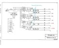
This is the general ouline of the unit

refrencelink schematic pg1.jpg


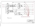
These are the 2 main pages i've followed and what i have replaced is shown ( I also replaced U200 - U207 transistors as a matter of course as they were out of the board and I had spares )

refrencelink schematic pg2.jpg
This page relates to Transformer 1 ( T101 on the schematic above)
refrencelink schematic pg3.jpg
If i haven't replaced it then it was within it's parameters after removing it from the board to test.

I shall post results of T102 testing soon
 
Check all of the filter caps after the rectifiers. They would have been hit with double the intended voltages.

Say the plus and minus twenty something supplies had 25 volt rated caps, being hit with voltages way above their rating may have damaged them?

Concerning the second picture with the regulator circuits the odds are fair that they survived and are OK.

Are the voltages you marked in red the actual voltages or the schematic indicated voltages?

Is the unit built all on one circuit board? Can you provide the link to the schematic you found?

Pictures of the guts would help me/us provide suggestions on how to possibly trouble shoot.

As an example is it easy to disconnect the secondaries of the transformers from the circuit board. That way you could test and trouble shoot one supply at a time.

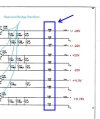
What are these components? (blue box) Are they easy to access as test points or remove for isolation?
psaud.jpg
 
this will be a fun diagnostic journey.

i typically freak out when vintage tube gear (110v/115v/117v) is plugged into 120v or higher (122-128v) due to the step-up ht tap secondary.

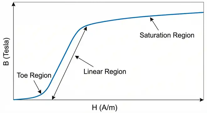
in your situation, the mains txf(s) took a big hit which more than stressed the b-h curve of the power magnetics i.e. beyond saturation in terms of flux density. no idea if there is a thermal fuse amongst the transformer (txf) windings.

watching each txf output using dim bulb and a variac, start low at 50% of whatever the mains switch/wiring is set to. watch the ac voltage output as the variac gets turned up to 75% of the mains setting, watching for a linear rise. might want to find the spec sheet for each regulator, some are rather robust and can handle a short term hit on the front end. as mentioned earlier, cap voltages also should be inspected even though it wouldnt hurt to do a full recap (electrolytics).

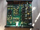
1946325-0954c0b2-ps-audio-reference-ls-reference-dacpreamp.jpg

found a photo from a sold advert, several electrolytics in the system.


Screenshot 2026-09-02 at 12-33-34 refrencelink schematic pg2.jpg (JPEG Image 900 × 741 pixels).png
looks like there is a terminal block to adjust the mains from 120v to 240v (parallel vs series primaries).

However when i took it off the DBT and plugged it straight in, the fuse would blow.
were you feeding it 120v or 240v vs internally setting?
 
this will be a fun diagnostic journey.

i typically freak out when vintage tube gear (110v/115v/117v) is plugged into 120v or higher (122-128v) due to the step-up ht tap secondary.

in your situation, the mains txf(s) took a big hit which more than stressed the b-h curve of the power magnetics i.e. beyond saturation in terms of flux density. no idea if there is a thermal fuse amongst the transformer (txf) windings.

watching each txf output using dim bulb and a variac, start low at 50% of whatever the mains switch/wiring is set to. watch the ac voltage output as the variac gets turned up to 75% of the mains setting, watching for a linear rise. might want to find the spec sheet for each regulator, some are rather robust and can handle a short term hit on the front end. as mentioned earlier, cap voltages also should be inspected even though it wouldnt hurt to do a full recap (electrolytics).

View attachment 3828746

found a photo from a sold advert, several electrolytics in the system.


View attachment 3828755
looks like there is a terminal block to adjust the mains from 120v to 240v (parallel vs series primaries).


were you feeding it 120v or 240v vs internally setting?
Thanks for that picture it answers a couple of my questions.
YES all one PC board.
Not real easy to isolate the primary side of the transformers for troubleshooting as they are soldered to the PC board.
 
Back
Top Bottom