• The move to the new server is done. There are some software and database maintenance updates in process. This has us passing the hat around to help out. We appreciate any donations. Seriously, even a dollar helps. The payment page may be found here - https://www.audiokarma.org/support.html

QSilver

Super Member
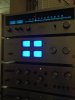
I got this today to add to my quadraphonic collection and to maybe try bi-amping some speakers. Everything looks reasonable inside although someone has sabotaged the front speaker outputs.

I powered it up and I've been trying to set the offset and idle current but I'm have problems....

I cant seem to be able to get it up to the idle current of 0.1V (100mV right?) I've not had a pioneer amp that whats so much idle current and I tried lifting it up to 80mV which took almost the entire trimmer pot on each amp.

The unit kept flicking in and out of protection but I've managed to set the dc offset which is under 10mV on each amplifier but again, I've almost had to turn the trimmer at least 3/4 of the way aroudn to get to set it on 3 of the 4 amp boards. The idle current doesn't seem to stay set after powering off.

I'm looking to recap this amp anyway due to the age its well overdue. Something else I noticed was that Q5 through to Q10 on each board are getting hot when its left idling. Is there some bad transistors somewhere or some big leakage from a cap or am I just not being brave enough to keep turning the trimmer?

It struck me as odd to think that the idle current wouldn't be getting near to its working voltage with the trimmer almost fully around...

Hopefully someone can point me in the right direction.
 
Register to hide this ad
The 100 mV set point is across a pair of 0.5 ohm resistors (in series), making the idle current 100 mA. That does seem pretty high. It is what the manual calls for. I have one of these amps, but it is buried. Maybe EchoWars or MarkTheFixer has some experience with these. It really does sound high to me. At 100 mA of idle current, your output drivers will get pretty toasty. I would lower your idle current to something reasonable, for now, like 30 mA (0.03 v between pins 5 & 9 on the amp board(s)). Having too little idle current will result in some residual crossover distortion, but little chance of damage. Having too much idle current could result in disaster.

The manual for the QM-800A amp has amp boards with different drivers, but similar topology. The setting for that amp is 20 mV to 60 mV, also across a 1 ohm resistor combination. It is not the same amp, and has several significant differences, but this is all I can offer.

The QM-800 service manual I have includes no errata sheets. Any design or operational changes are hidden from my view.

Errors in Pioneer service manuals are pretty rare. Maybe this is one that got corrected in a subsequent errata.

Good luck,
Rich P
 
Last edited:
Thanks Rich, I'm glad its not just me who thinks its high. The drivers and outputs were getting toasty - I'll try backing it down to 30mV for now until someone else chimes in. I had been measuring between pins (5+9) and (6+10) on both amplifier boards. I hadn't looked into the QM-800A - I thought it might be a bit different due to it being one of their revision ones like the QX-8000A but its interesting the the idle current is quite a bit lower.... I've noticed the VU for the front left channel floats a little too, but when I tap it, it either floats more and stops floating...

It keeps going in and out of protection too - I have managed to get the DC offset on each amp down to less than 10mV measuring between pins 7 to ground and pin 8 to ground on both amplifiers - even when in protection they are still low....
 
Last edited:
Thanks Rich, I'm glad its not just me who thinks its high. The drivers and outputs were getting toasty - I'll try backing it down to 30mV for now until someone else chimes in. I had been measuring between pins (5+9) and (6+10) on both amplifier boards. I hadn't looked into the QM-800A - I thought it might be a bit different due to it being one of their revision ones like the QX-8000A but its interesting the the idle current is quite a bit lower.... I've noticed the VU for the front left channel floats a little too, but when I tap it, it either floats more and stops floating...

Measure the voltage to the meter in question. If there is voltage, compare it to the other meters. If the other meters are not biased in the same way, meter drive is questionable (maybe fractured solder joint). If all are getting the same voltage, or lack of same, then the meter is likely sticking mechanically (parts unit time). The meter could be sticking due to lack of use and some corrosion (unlikely but possible I guess), let her bounce a while before seeking a replacement. It might clear up over time and use.

As for looking at one of my amps, both of mine are QM-800As as it turns out, so no help there. The QM/QC series come from worthy stock, from the design group that produced the SA/TX-9100 series, and, as such, have similar styling and quality. When fully restored, you should be very happy. The TX-9100 will go nicely with your set.

Post back on your results. Inquiring minds want to know...

Good luck,
Rich P
 
As soon as I managed to coax the unit out of protection I took some measurments on the VUs. The protection circuit looks like it might have issues - the DC offset on all amps is neaer 0mV now but TP1 and TP2 on the protection board see 300mV and when in protection exceed 2V....

I connected a audio generator to the front left and right amp boards and the readings I got on the wire feeding the VU match quite closely in mVDC. It's not floating at the moment but just dead. Maybe the next step is to check where the second lead (likely ground) is heading to?
 
As for looking at one of my amps, both of mine are QM-800As as it turns out, so no help there. The QM/QC series come from worthy stock, from the design group that produced the SA/TX-9100 series, and, as such, have similar styling and quality. When fully restored, you should be very happy. The TX-9100 will go nicely with your set.

I didn't know about that, thats good to hear. I took a little bit of a shot with this unit, it looked nice and from what I had read it sounded like it might be quite good... restoration is what I was thinking of doing - I've already ordered the caps and new trimmers for the whole unit.
 
I didn't know about that, thats good to hear. I took a little bit of a shot with this unit, it looked nice and from what I had read it sounded like it might be quite good... restoration is what I was thinking of doing - I've already ordered the caps and new trimmers for the whole unit.

Recapping is not a repair operation, so do not recap until you have the unit fully functional. Once that is true, recapping is an effort toward longevity.

As for your current problem, I do not have time for remote troubleshooting at this time. I have restorations stacking up on my local bench. Also, I have no experience with your particular model. MarkTheFixer is the remote troubleshooter in this neighborhood. Contact him and see if he can lead you to joy. I'll watch this thread and contribute pertinent info as I may have it available to give. Do keep us informed what you find.

Good luck,
Rich P
 
Recapping is not a repair operation, so do not recap until you have the unit fully functional. Once that is true, recapping is an effort toward longevity.
Thanks, I didn't think that re-capping would make the problems go away, but I thought it might help stop any chances of excessive leakage or chances of oscilation. I can see a few sanyo caps in there and they all seem to be original to 1971!

As for your current problem, I do not have time for remote troubleshooting at this time. I have restorations stacking up on my local bench. Also, I have no experience with your particular model.
Thanks for your input, its very helpful. My thoughts on ordering the new trimmers was that I think that at least one or two may be contributing to problems setting DC offset on some of the amps so I ordered some bourn's multiturn 5k for those.

From the manual, it says that you have to disocnnect the amp inputs from the protection board (I am thinking you need to disconnect the wires from the other proterction board too, on pins 5 and 8 on the main protection board AWM-011) and then you adjust VR1 on AWM-011 for 0V and then reconenct everything. I tried to bypass this stepa s I didn't want to make a mess of the wire wraps on the pins. I set the DC offset on each amp between its output pin and ground. (7 or 8 and then to ground) and then checked the voltage present at the test points. But this still floats around 300 and I cannot get it lower. Thats why I'm thinking I have issues in the protection circuit... or maybe I did something stupid and I cant adjust it in the way i did...

I'll go and see if I can get that VU to work again while we wait for someone to chime in about the idle current etc.

I'll post back with my findings and read up on the protection circuit.
 
Still not managed to look into the VU problem but I think the protection circuit is being triggered by the front-right amp section. At first it will operate but after 5 minutes or so the offset starts to go crazy, ranging from 10mV to 120mV at this point the protection board test points go off the 200mV scale on my DMM too...
 
I finally found my QM-800 thread from when MTF helped me with mine. It might possibly help you in restore.

Thanks Noodle! I had already found your thread and I had been reading through it. It seems that it's one of the only diagnostic threads I could find about the QM-800 and you did mention that you set your idle current to 0.1V... which is 100mV correct? Is that what your reading is between pins 5 & 9 and 6 & 10? I see that there is a transistor list on there too which is helpful. Maybe it would be best to replace the differential pair etc. I'm leaning towards the DC offset trimmer being faulty on one of the amps - I get an unsteady reading and then after I tap gently press or touch the trimmer with a screw driver, it sometimes stabilises...

All my VUs still have their tungsten bulbs at the moment... was and LED conversion difficult?
 
Thanks Noodle! I had already found your thread and I had been reading through it. It seems that it's one of the only diagnostic threads I could find about the QM-800 and you did mention that you set your idle current to 0.1V... which is 100mV correct? Is that what your reading is between pins 5 & 9 and 6 & 10?
All my VUs still have their tungsten bulbs at the moment... was and LED conversion difficult?

I just measured my readings and they vary from 17mV to 20mV, on both amp boards. I should've at the time replaced my trimmers, still may.
The top two LEDs were fairly easy, but the bottom two were rather a pain.
 
I just measured my readings and they vary from 17mV to 20mV, on both amp boards. I should've at the time replaced my trimmers, still may.

That sounds more like it, I'll set mine to around 20mV for now.

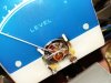
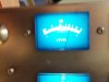
I've got the VU working again - I took it apart and found that at some point one of the small wires going from the binding post to the meter coil had been damaged so I neatened it and re soldered it. The tape holding the meter together had sompletly let go too, so i refreshed that - probably would be best to re-tape all the meters but I left it with that oen for now. Put it all back together and reassembled the front of the chassis and then had to coax it out of protection again.... no dc ofset issues showing on the amps - just the protection board....

Once I got it out of protection again, I fed a signal in through the amp to the VU and we have deflection! Now that all the meters are back, I guess its time to take a look at the protection circuits etc... but first, I'll just lower the idle current to 20mV...
 

Attachments

  • 20151009_223232.jpg
    20151009_223232.jpg
    72.6 KB · Views: 4
  • 20151009_225728.jpg
    20151009_225728.jpg
    63.2 KB · Views: 3
  • 20151009_234553.jpg
    20151009_234553.jpg
    49.4 KB · Views: 3
How are you coaxing it out of protection?

New trimmers are a good idea on old amps. On some, it is best to replace them before trying to adjust. Some amp designs did not provide protection for trimmers that are dirty enough to intermittently open up as you rotate them...BOOM!

Be careful to set the new ones to values that the old ones were set to, for a good, ballpark starting point.

Enjoy,
Rich P
 
Thanks for the advice Rich, if I ever change a trimmer I do usually adjust it to a similar level to the old one if I can. I do have some 100 Ohm trimmers for the idle current I think. Bourns single turn sealed ones... I've got some 5k multi turn ones on their way for the DC offset.

How are you coaxing it out of protection?

At the moment, if it won't come out of protection I take readings of the DC offset at each amp output between pins 7 0r 8 and ground. These are usually low, 10mV or lower. Then I check the test points on the protection board and this is usually going up and down from 1V to 400mV. If I then adjust VR1 on the protection board which controls the centre point on the protection board, the voltage will sometimes suddenly drop down to 300mV and lower and the protection will come out and then I can adjust it down to aroudn 100mV.

If I leave DMM probes on TP1 and TP2 and use another to check the amps, the voltage between TP1 and TP2 will jump after five munites or so which kicks it back into protection. Sometimes it settles again and sometimes it doesn't but when I check the amps' DC offset, they are all ok.

Hope I've been clear enough... sometimes its difficult explaining things like this.
 
Is it sensitive to tapping around? If so, you just might have a cold or fractured solder joint or two. I remember you stated something about a sensitivity to tapping.

Enjoy,
Rich P
 
Is it sensitive to tapping around? If so, you just might have a cold or fractured solder joint or two. I remember you stated something about a sensitivity to tapping.
I'll take a look at the amp boards and see if I can find any old solder joints. I might put in the new trimmers while I'm there just to make settings things easier. I tried connecting the rear channels up to speakers and a tone generator. The rear left sounded ok but rear right was very badly distorted.Havn't tried the front channels yet because whoever had it before me has changed the speaker terminals....
 
Cap coupled amp.
Scat shows 30mA Idle.
Set VR1 and 2 to half the collector voltage of the of the other output transistor. (Voltage reading taken on the case of the outputs)
Set VR3 and 4 to .0075v across one of it's emitters. (.030/2=.015x.5=.0075)
Doesn't seem like much but increasing the idle will only add heat when no audio is coming through.
So bump it up a bit to 10 to 13mV's?

After the above suggestions:
Deox the controls.
Replace the 2SA572 differential pairs with a matched set of KSA992's.

No experience on this amp but have some on other Pioneer cap coupled setups. (Love'm)
 
Cap coupled amp.
Are you sure this is a cap-coupled amp? My understanding of those is that they have a single voltage rail and slew between B+ and 0V with a capacitor blocking the DC. This amp has no output capacitors and a rectifier and two capacitors per amplifier board. I have +30V and -30V to the amp boards. So isn't it a OCL amp?

I'll try putting the current back up to 30mV again. Thanks for your information on the transistors too. If this isn't a cap coupled amp then should I still continue?
 
Your right, I was jumping to a conclusion.
That idle current spec'ed in the SM is crazy! But: They are wanting it across both emitters (1 ohm) :idea:
 
Back
Top Bottom