• The move to the new server is done. There are some software and database maintenance updates in process. This has us passing the hat around to help out. We appreciate any donations. Seriously, even a dollar helps. The payment page may be found here - https://www.audiokarma.org/support.html

QR-6500 / QRX-6500 : stuck with a different version of the F-1322 FM decoder

david winter

Classical music lover.
Hello,

I am close to finish restoring a QR-6500 (serial is 211091683 if this can help with differences / mods).
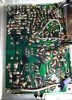
I need to verify the position of a strap (see picture below) on the solder side of the F-1322 decoder board.
The service manual seems to have the right schematic (at least something very close to it) but the component layout shown on Page 18 correponds to another version with several different parts (of which those circled in read on the pictured). Thus I can't easily ensure that the strap is correctly put.

Anyone has a photo of his board to compare (supposing it's the same version), or the right schematic ?

Thanks !
Dsc_1985.jpg
DSC_1987.jpg
 
Register to hide this ad
I forgot to mention that the right side of the strap (red arrow) is correctly soldered. It goes to the + of a 1µF electrolytic, itself in series with a 100K resistor.
The problem is with the other side which was put to the wrong place as per picture: cathode of D491 / + 100µF/25V / emitter of 2SA562.
The question is where it should be put back.

In the meantime I replaced all 2SC871 / 2SC711, tested the remaining transistors (all ok) and finished recaping (replaced four 1µF electrolytics by film caps).

Any hints appreciated ! Thanks.
 
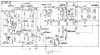
I am struggling with a very poor copy of the schematic for the board in question (?) - if you have a better copy it should be easy for find where the misplaced link goes?

upload_2023-4-3_14-34-25.png
 
Thanks for posting this. It's version D, which differs from my board which has a few differences, including a 330K resistor between pins 4G and Gnd. This 330K is in series with the 47K (in place of D409) going to the base of TR416 (2SC711) and the - of a 0.1µF electrolytic, which + goes nowhere (could be the strap but can't make sure of it).

Here's your schematic. It's used in the QRX-6500 but not the QR-6500.


F-1322-D.jpg
 
Last edited:
Thanks, that is much better but I am still making no sense of your directions as to where the correct link is connected - referred to the posted schematic, If we knew that we could make an educated guess as to where the misplaced link would go.

If you make a mental note of where the correct link goes, spin the board over and note the connected components and pinpoint it on the schematic, then we would be making progress. At the moment I can't find D409, or a 330K resistor, and can't be sure which transistor is TR416 (the middle one of the group of three in the centre, bottom of the schematic?) . You are the only one that knows which components the correct link is connected to..... do you see my difficulty?

Might be better to wait for someone to respond who is familiar with the QR/QRX6500 or someone who owns one.
 
Last edited:
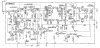
The board has several differences:
- R461 replaced by 1µF / 25V (in series with the 47K as explained above)
- R468 replaced by 100µF / 25V (C493). This is visible on Rev. C schematic below.
- TR415 is confusing because its reference should have been put closer to it instead of next to a NPN. I edited the schematic and moved the references to avoid confusion.
- TR417 is removed on my board. TR415 (2SA562) has its emitter going where the base of TR417 (2SC711, removed ) used to be. Consequently, TR416 only has a R463 (10K) between its collector and the base of TR415.
- There is a 0.1µF electrolytic which - is at the base of TR416. However, this cap isn't on the Rev C schematic, and its + goes nowhere.
- There's a mistake on the schematic with the 0.68µF electrolytic near VR402: its + goes to VR402 and its - is grounded. Schematic puts the - at the main power after R465 (47R)...

F-1322-C.jpg
 
Last edited:
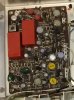
The F-1322 is the MPX board. Here is a picture of the tuner tray in my QR-6500 when I had the receiver apart for some re-capping work. I don't have a picture of the underside. I don't know if this helps or not. I have not worked on the tuner in my unit.

Tuner.jpg
MPX board.jpg
 
The F-1322 is the MPX board. Here is a picture of the tuner tray in my QR-6500 when I had the receiver apart for some re-capping work. I don't have a picture of the underside. I don't know if this helps or not. I have not worked on the tuner in my unit.

Your board has the same mods than mine. All other photos found around the web didn't match.
Do you still have the receiver ? There are holes on the chassis edges which, with proper lighting, allow seeing the underside of the board partially.

Thanks for your photos!
 
Yes, I do have the receiver. It's on the shelf at the moment. So you want to see where the wires on the solder side of the board are attached? I could open it up and get a picture for you. It's pretty easy to get the tuner out.
 
Thanks, that would be great ! :thumbsup:
If you look at my initial pictures, you will see a jumper on the solder side (red arrow). All I need to know is where it goes as it was put back incorrectly. Its end near the border is correct, but the other isn't.
 
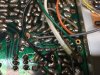
Here are the pictures. One of the whole board, and one zoomed in on the area you are interested in. Seems to me the wire in clear plastic is connected the same as mine. Comparing the your photo to mine the only thing I don't see in yours is the green wire connected to the pad right next to the the multi-strand white wire. Do you have that green one?

IMG_1492.jpg IMG_1493.jpg
 
Thanks a million times for taking the time to picture your boad. That's really helpful :)
The green wire is barely visible on the far right of my picture, just between the white and black wires. Looks almost black.
Time to put everything back in place, and check the regulated psu.
 
Back
Top Bottom