
• The move to the new server is done. There are some software and database maintenance updates in process. This has us passing the hat around to help out. We appreciate any donations. Seriously, even a dollar helps. The payment page may be found here - https://www.audiokarma.org/support.html

QSC PLX1202 Help

AyEss

Member
hey guys.. Recently bought a QSC PLX 1202 Power amplifier off ebay, faulty, To repair..

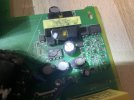
My fault finding has led me to believe the small transformer has blown, and gone open circuit..
Labelled T1 on schematics...
Service manual says that when U16 TOP210 chip is removed, there should be 15 ohms of resistance on Pin 1 and 2 of the primary.. But im getting a full-on open circuit when testing :(

Does anyone happen to know if replacements are available?
Im not sure what voltage specs it is.. Since im unable to test it to find out...

The small transformer is located at the corner of the PCB... Labelled T1, Next to U16 etc...

If i can find a suitable replacement, outputting the correct voltage etc... I will be happy :)

I am in the UK.. so 230v mains.. If thats any help...

IF anyone could help, id be most grateful... I havent been able to find a technical support Email address for QSC, to be able to contact them..
Im going to be P**sed, if i am unable to repair it, Due to not being able to find a small little transformer for it!!!

cheers
 

Attachments

  • IMG_0994.JPG
    IMG_0994.JPG
    96.8 KB · Views: 10
Register to hide this ad
That little transformer & TOP210 make up the low current bias supply and there may be far more damage down the line. My experience with QSC has always been very positive over the 35 years I've own their amps. Parts are "reasonably" priced and always available but honestly I hope you didn't pay too much for that PLX series. They don't have the punch of the big boys and are best at near or full power output because of their switching power supply topology. I own two of the ISC300Ti and two of the vintage 1400's. Basically the PLX uses the same power amplifier section layout as the earlier ISC with some minor differences and used a burly PWM switcher in place of the muscular toroid and large capacitors that give them the high current low impedance punch.

You could sub in your own +16V from an external supply to the top of C139 and see if things come alive, that transformer can be found in other electronics including those plug-in USB charger bricks, their output voltage is based on the pulse width energy needed to maintain the desired outgoing voltage to the load compared with a zener reference in this case would be D66. DO check this before attempting to use an external power supply.

The primary of that little switcher comes from the end of N381 and is basically unlimited, my question is was the amplifier configured for the UK 220V mains with the correct plug or is this a case of a US spec configured for 120V that was inadvertently plugged into the UK mains without the supply jumper set? Reason I ask is if configured for 120V and fed 220V its going to hit that voltage doubler and come out well over 480V and there's no telling how much damage would be done. This could also be a case of where that little TOP210 overheated and popped due to a high ESR leakage capacitor C138. Either way finding a suitable sub isn't difficult in this day & age of disposable chinese make electronics that uses switchmode power supplies. You may also find that little TOP210 in one of those brick chargers as well or possibly a dead DVD player, they are a very popular part.

Good luck and I will check back periodically, I have over 25 years of experience with switchmode supplies.
 
That little transformer & TOP210 make up the low current bias supply and there may be far more damage down the line. My experience with QSC has always been very positive over the 35 years I've own their amps. Parts are "reasonably" priced and always available but honestly I hope you didn't pay too much for that PLX series. They don't have the punch of the big boys and are best at near or full power output because of their switching power supply topology. I own two of the ISC300Ti and two of the vintage 1400's. Basically the PLX uses the same power amplifier section layout as the earlier ISC with some minor differences and used a burly PWM switcher in place of the muscular toroid and large capacitors that give them the high current low impedance punch.

You could sub in your own +16V from an external supply to the top of C139 and see if things come alive, that transformer can be found in other electronics including those plug-in USB charger bricks, their output voltage is based on the pulse width energy needed to maintain the desired outgoing voltage to the load compared with a zener reference in this case would be D66. DO check this before attempting to use an external power supply.

The primary of that little switcher comes from the end of N381 and is basically unlimited, my question is was the amplifier configured for the UK 220V mains with the correct plug or is this a case of a US spec configured for 120V that was inadvertently plugged into the UK mains without the supply jumper set? Reason I ask is if configured for 120V and fed 220V its going to hit that voltage doubler and come out well over 480V and there's no telling how much damage would be done. This could also be a case of where that little TOP210 overheated and popped due to a high ESR leakage capacitor C138. Either way finding a suitable sub isn't difficult in this day & age of disposable chinese make electronics that uses switchmode power supplies. You may also find that little TOP210 in one of those brick chargers as well or possibly a dead DVD player, they are a very popular part.

Good luck and I will check back periodically, I have over 25 years of experience with switchmode supplies.
Hey, thankyou for you're reply.

Yeah i did assume that there could potentially be damage further down the line, But so far, everything i have checked, is testing fine..
IGBT's. Bridge Rectifier.. Near-by capacitors are what id say, within tolerance..

I did what the service manual stated, Removed the blown TOP210 (well, it crumbled off the board, and i just desoldered the legs out),
and checked resistance on the small transformer In location T1, But it tested as 0.01 ohms... dead short... When the manual states around 15ohms...
So i removed the transformer from the circuit, To get a more accurate reading.. and sure enough, still reads 0.01 ohms on Legs 1 and 2 of the primary..
So im now in need of a replacement T1 transformer :(
I found the part code in the manual, but every website i find, seams to be out of stock, Or not even remotely near the UK :(

Are there any other important things to inspect for damage? Around that area?
Im not overly amazing at electronics, I buy faulty amps for fun of learning. So if there are any specific areas that should be inspected, If you could supply the board location code (Q106 etc), that would be very helpful for me...

cheers
 
Well that little T1 transformer is not difficult to find if you're willing to think outside of the box. I don't know what you have for consumer grade electronics in the UK so I will do my best to parallel here. You might try looking at say a cellphone charger or small "brick" type power supply for a substitute transformer, maybe a DVD-BlueRay player would have something suitable. Thing is there is some tolerance in electrical values and most of what is used these days is "off the shelf", that TOP210 is commonly used in consumer grade electronics power supplies and is known to go into a thermal runaway. I'd maybe look inside a dead DVD or BlueRay player for the transformer. QSC calls this a "housekeeping" power supply and it is responsible for running the main switching power supply along with several of the safety circuits so it is essential that is functional, there is some margin to work with here in that the D66 zener sets the voltage and this sets the reference for pin-4 on the TOP210 thru the divider of R349 & R356. Once 5V is achieved on pin-4 the PWM will fold back the drive to keep up with the demand, using a transformer with a slightly different output will cause the TOP210 to compensate for this tolerance as it attempts to bring pin-4 to 5volts. Yes you can have your cake and eat it.
Some DVD players have multiple output transformers so you will have to follow the traces around, as a rule of thumb there will be a +12v, +5v and maybe a -12v or -5v in them. This is not as important as just knowing what secondary connections are for what ballpark voltages. Confused? Good! This is the learning part of the overall lesson.

SOooo... what I'd be checking first are all the diodes D-60 thru D69 for shorts, the zener D66 will need to be dynamically tested with a 12-15v power supply, 10k ohm resistor and known good DVM. It must read 10 volts. Next check Q99 which is a 2N3906 in a surface mount package for any shorts using the diode test function of a DVM and replace C138 with a low ESR part, 100uf @ 35V for some margin. These are available on Amazon as are many of the other parts you will need, I smashed open a USB type cellphone charger and found what looks like would work for replacing T1, it also had a surface mount version of the TOP210. It was a no-name charger that I found at work.
 
Oh okay... I just assumed that each transformer, Had different voltage outputs... So didnt want to find a random transformer for T1, and send too much voltage to the circuit.. :biggrin: - I am very new to electronics.. and this is my first switch mode power supply work ive ever worked on..
My first project, was a Vintage Peavey CS-1000 power amp, Which was the generic power supply design... Big transformer, Filter caps, Bridge rectifier, which went to each channel PCB's. haha... Was a very easy repair... A couple of Shorted T-03 transistors, and a couple of out of tollerance Emitter Resistors....

Working on this QSC, with the power supply being how it is.. Is kind of, Over my head. haha.

I do however, Have one of those Chinese Ebay 230v to 12v power supplies, Sitting in my cupboard, (Like pictured below) That im sure has a small transformer in it...

I have replaced the TOP210 chip, and fitted a Turned Pin socket, for easy future replacement, and i have also ordered a couple of the CNY17F-1 chips too. Simply because the legs look very grey and oxidized (may aswell, as they are only a couple of £) So going to socket those too..
Every component around the area, I have checked, and seams to be fine (the 3 pin SMD Diodes are confusing though, being 3 pins), So will have to google a way to test them with a multimeter...
 

Attachments

  • s-l1600.jpg
    s-l1600.jpg
    193.7 KB · Views: 3
Transformers are going to have different voltage & current ratings but there is *some* wiggle room here being it's a "standard" voltage. I'm not saying any transformer will work but this may get you into the ballpark enough to see what else may be going on.
 
Transformers are going to have different voltage & current ratings but there is *some* wiggle room here being it's a "standard" voltage. I'm not saying any transformer will work but this may get you into the ballpark enough to see what else may be going on.
ahh okay, i get you :)

Ive found a proper replacement, from QSC. I think i will just order that, Even though its from the USA, I think id be better off ordering the correct replacement part, So im not taking any chances...
I have been checking around the board, in the location where the TOP210 chip is located, And as far as i can tell, Everything is checking out just fine... Most are in the Kilo Ohm and Meg ohm range.. So definitely no shorts that i can see..

Got a TOP210 chip on order, Aslong as the Turned Pin IC sockets. Hopefully thats all thats wrong with it..
I wasnt aware that transformers can just fail on their own... But its definitely looking that way
 
I'm thinking this is only the tip of the iceberg and I'd be looking at C138 as a possible root cause of the failure IF the amplifier had NOT been configured for 120V and plugged into a 220V feeder. My reason for C138 is a standard electrolytic cap is going to be highly reactive to the 100KHz square wave coming from the transformer and will eventually become a load itself. The TOP201 is rated for 8 watts giving little margin before overload. Two theories for the failure; C138 became reactive and overloaded TOP210 and this cooked T1, the other is the input was strapped for 120V and someone fed it 220V blowing TOP210... Its been heat cooked so I'd say it's been working hard for quite a while.
 
I'm thinking this is only the tip of the iceberg and I'd be looking at C138 as a possible root cause of the failure IF the amplifier had NOT been configured for 120V and plugged into a 220V feeder. My reason for C138 is a standard electrolytic cap is going to be highly reactive to the 100KHz square wave coming from the transformer and will eventually become a load itself. The TOP201 is rated for 8 watts giving little margin before overload. Two theories for the failure; C138 became reactive and overloaded TOP210 and this cooked T1, the other is the input was strapped for 120V and someone fed it 220V blowing TOP210... Its been heat cooked so I'd say it's been working hard for quite a while.
Its a 220v amplifier bud. Says "230v UK Mains" on the back...
 
So... urgh.. Cant find a replacement T1 transformer anywhere... *rolls eyes*

Every website, is in america.. and out of stock...
QSC directly, have them.. But dont sell to end-users......

So what do i do now?!?!

Its a bias supply transformer, QSC part code: XF-000064-00
Apparently for the PL218 amplifier too....
 
I wouldn't say that, I'm just a guy who has stepped on a few landmines in life and learned how not to step on them again.
Would you happen to know the input and output voltages on the T1 transformer?
Would it be 230v Input? (since mine is 230v amplifier here in the UK)
and what about the output voltage?

I am doing an ebay search, of SMPS transformers... Loads come up, But different voltage versions... I dont know what the QSC T1 transformer is meant to be...
 
Transformers are going to have different voltage & current ratings but there is *some* wiggle room here being it's a "standard" voltage. I'm not saying any transformer will work but this may get you into the ballpark enough to see what else may be going on.

I have found it out to be a TSD-1135 transformer..... But i still cant find them forsale!!!!
 
Premier Magnetics has them for $6.05USD along with AVNET Europe.
i do recall seeing a website, with a name like that, But if i remember correctly, Each time i found it on google, and clicked the link, It just gave me the specs sheet.....
Or if i click the BUY button, for it, On Premier Magnetics.. It sends me to AVNET website home page, and nothing else?!?!
Possibly because im in the UK?!?!

If you could kindly provide the link, for the exact transformer that will be a good part for my amp.. I would really appreciate it :)
 
Last edited:
I get the same thing so I don't think it's a UK thing, don't know what to say other than to see if you can find something with similar specs.
 
Im going to be honest bud... I have absolutely no clue what to look for....
Ive never had to work around transformers etc before..... Only repairs ive ever done to amplifiers, are shorted transistors, OPAMP modifications, Re-capping, DC Offset adjustments etc....

If im correct, The t1 transformer is spec'd at 264v input, 5-15v output... Its 8 pin through-hole.... and thats the extent of my knowledge on it haha
I get the same thing so I don't think it's a UK thing, don't know what to say other than to see if you can find something with similar specs
 
Well you're in luck with this one, the transformer is dependent on the duty cycle and not so much the voltage.
 
Back
Top Bottom