• The move to the new server is done. There are some software and database maintenance updates in process. This has us passing the hat around to help out. We appreciate any donations. Seriously, even a dollar helps. The payment page may be found here - https://www.audiokarma.org/support.html

Quad 303: why are you blowing the main fuse?

Idle current is a bit off in one channel. Supposed to be 10mA, measuring 14, and it is 14mA for the 1/3 of the pot, then it goes up.

 
i generally use croc clips and some wire to get a signal into amps if i haven't got the correct plugs .as long as your grounds are good it shouldn't hum much if at all .
i always check dc offset before connecting speakers unless its cap or transformer coupled output .
the bias might settle down when it stabilises .
when was it last in use ?
 
i generally use croc clips and some wire to get a signal into amps if i haven't got the correct plugs .as long as your grounds are good it shouldn't hum much if at all .
i always check dc offset before connecting speakers unless its cap or transformer coupled output .
the bias might settle down when it stabilises .
when was it last in use ?

It is cap coupled. Bias is good in the other channel now, and everything is set. Except for the first channel bias.

I don't know when it was last used, but it could have been a while. The owner tried a couple fuses too before bringing it to me I think.
 
FYI, 100 watt is usually the max wattage light bulb used with a dim bulb tester.

Main filter capacitors are main suspect!
 
So I put the jacks in nice and neatly, and no sound! And now, no voltage to the rectifier. But voltage at the power cord.
 
blown fuse then or bad power switch .. voltage selector maybe .
power to the transformer primary ?

Broken wire at primary side of transformer. Back in business. Passed sound check.

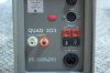
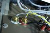
Here are pics of the jack install.
 

Attachments

  • 303-0.jpg
    303-0.jpg
    53.9 KB · Views: 35
  • 303-1.jpg
    303-1.jpg
    59.6 KB · Views: 33
Last edited:
nice job .i may well have a 4 pin din plug here .. seem to remember some stereo mic.s having them ..
normally 5 pin for audio in / out .
 
a variac would be helpful here. if nothing else to save on fuses. using a VOM or DVM on X1 ohm scale im bettin' one of the AC line Rectifier diodes is dead shorted. it would help if i could see them. is this full wave or full wave bridge set up???

if you can disconnect the rails from the diodes. insert another fuse and pray.

if the fuse blows....diode

if it dosen't blow one of rails is shorted. measure again X1 scale from each rail to chassis ground. good luck
 
a variac would be helpful here. if nothing else to save on fuses. using a VOM or DVM on X1 ohm scale im bettin' one of the AC line Rectifier diodes is dead shorted. it would help if i could see them. is this full wave or full wave bridge set up???

if you can disconnect the rails from the diodes. insert another fuse and pray.

if the fuse blows....diode

if it dosen't blow one of rails is shorted. measure again X1 scale from each rail to chassis ground. good luck

See previous posts, fixed. And the DBT helped save fuses.

The preamp sound distant and weird in one channel, other channel is good.
 
The channel issue is due to this 5 pin/RCA splice I was given with this thing. Wired wrong.

Resplicing the cable correctly worked. Playing now. I'll run it for a bit then check that bias again.
 
Last edited:
So, are you plugged directly into the wall now? Why was it blowing fuses?
Yep, hooked to wall, playing now.

Theory A: main caps got reformed on the DBT and stopped shorting.
Theory B: supply voltage was set too high, and drew too much current on powerup.
 
Something is a bit off on one board. At idle, with the bias pot all the way down, the board draws 10mA through the supply. The good board draws none. With the good board, when the board is set to draw 10mA, voltage across an emitter resistor is 5mV. In this board, when the board is drawing 10mA, the voltage across the emitter resistor is 0mV. When I turn the bias pot past half (to about where it is set on the good channel), the voltage across the emitter resistor goes up as it should.

In short, bias is fine but something is drawing 10mA at idle when it shouldn't.
 
which version of the 303 is it, early or later, are the overcurrect diodes ok ? how do you know the board is taking 10ma

The driver board is the later version. Issue 10 in the SM.
Which diodes are the overcurrent diodes?

To set bias, you insert the meter inline with the supply. And it draws 10mA with the bias at 0. Checked voltage across the emitter resistors, this showed the bias was 0. But the board was still drawing 10mA. The other board draws none when the bias is 0.
 
Back
Top Bottom