• The move to the new server is done. There are some software and database maintenance updates in process. This has us passing the hat around to help out. We appreciate any donations. Seriously, even a dollar helps. The payment page may be found here - https://www.audiokarma.org/support.html

Question re: Marantz 8b high voltage power supply diodes

junkscience

New Member
Question regarding Marantz 8b high voltage power supply HV PSU diodes replacement

I am restoring a Marantz 8b amplifier.

It is a straight forward decision to replace the selenium rectifier.

It seems that this would be the opportune time to also replace the high voltage power supply diodes.

My question is: can I substitute just two modern HV diodes for the legacy pair of series diodes?

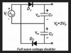
Looking at the Marantz schematic (attached below), there are four diodes. Curiously, on closer look at the schematic this does not appear to be a typical full waive bridge, is it? Rather, it appears that the Marantz 8b HV PSU is Full Wave Voltage Multiplier. This circuit is usually implemented with just two (2) diodes. Whereas the Marantz 8b has a pair in series.

* Was this originally implemented because of limitations in the legacy diodes?
* Is there any advantage to daisy chaining diodes in series?
* Can I replace the four (4) with two (2)?

Thanks for any help!
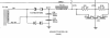
MARANTZ MODEL 8B (detail).png
Full wave voltage doubler (generic).png
 
Last edited:
Register to hide this ad
Yes, that is a voltage doubler. The 2 diodes in series are likely to meet the voltage requirement. If you know the diode part numbers you can look them up. Yes you can replace with single diodes with the appropriate voltage and current spec. If you can't determine the original diode specs, just use diodes of 1kV 1A or better and you should be fine.
 
Yes, that is a voltage doubler. The 2 diodes in series are likely to meet the voltage requirement. If you know the diode part numbers you can look them up. Yes you can replace with single diodes with the appropriate voltage and current spec. If you can't determine the original diode specs, just use diodes of 1kV 1A or better and you should be fine.

Thank you dgta!

For other Marantz 8b restorations that may follow this link. User Buck Rogers kindly also replied,
That should work fine.

Only difference is you will gain another .5 to .6 volts.

Check out HexFet diodes (Fast switching) they are a common audio upgrade.

Buck

Thank you both!
 
In 1995, VAC (Valve Amplification Company) was contracted by Marantz to produce replica Model 7’s, 8b’s and 9 monoblocks. Marantz could not have chosen better. Later, sometime following Marantz' discontinuing the replicas, VAC produced the Auricle, an improved version of the 8b. The contemporary audiophile trade press was appropriately raving of Keven Hayes' improvements, “U-N-B-E-L-I-E-V-A-B-L-E was the first thought that went through my mind …" wrote Jim Olson in Positive Feedback.

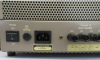
Attached is an ebay photo. Found in the later 1995 reproduction is the evolution to speaker-out binding posts, IEC 60320 cord socket; and visible on the underside is the revised bias meter fittings.

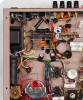
Also attached is a wiring detail from a photo found on Pinterest. Beautiful work. I believe this is the VAC replica, as note the new Marantz branded capacitors and chassis updates as shown in the ebay photo. (It might also, less likely, be the Auricle Mk 1?)

* The wiring photo shows just two modern rectifiers. QED.

* Also of interest, taking up the position of the absent legacy series rectifiers, are now two capacitors. (Caveat, it is not clear were the new capacitors are placed in the circuit). VAC's Keven Hayes is fastidious in voicing circuit changes, and it is a tantalizing lead for consideration of, later, additional modifications.

HV PSU circuitry, VAC Marantz reissue or Auricle.png
 

Attachments

  • Marantz replica.png
    Marantz replica.png
    499.7 KB · Views: 39
Last edited:
Question regarding Marantz 8b high voltage power supply HV PSU diodes replacement

I am restoring a Marantz 8b amplifier.

It is a straight forward decision to replace the selenium rectifier.

It seems that this would be the opportune time to also replace the high voltage power supply diodes.

My question is: can I substitute just two modern HV diodes for the legacy pair of series diodes?

Looking at the Marantz schematic (attached below), there are four diodes. Curiously, on closer look at the schematic this does not appear to be a typical full waive bridge, is it? Rather, it appears that the Marantz 8b HV PSU is Full Wave Voltage Multiplier. This circuit is usually implemented with just two (2) diodes. Whereas the Marantz 8b has a pair in series.

* Was this originally implemented because of limitations in the legacy diodes?
* Is there any advantage to daisy chaining diodes in series?
* Can I replace the four (4) with two (2)?

Thanks for any help!
Back in time when 8b was designed, there was hard to come by with diodes with 1000V reverse rating. Now they are very common. The best will be a choice of soft recovery diodes.
 
I use the 1N5408 diodes, just two of them, in my 8B. Soft recovery is fine, but not necessary due to the low 50Hz/60Hz frequency. I have not seen any switching anomalies as the standard diodes shut off on the reverse voltage part of the cycle. 1N5408 is not a soft recovery type.
 
A PIV of anything greater than the delivered B+ will serve. The 600V types are in excess, and 1200V easy to come by. For this type, 1200V, SiC Schottky would be preferable as they are as close to zero recovery time as is possible to acquire. 5A from Cree are less than $10 each, and when compared to GZ34 cost are peanuts.
cheers,
Douglas
 
For the selenium replacement see:
http://www.w3hwj.com/index_files/RBSelenium2.pdf

For the Power Supply Unit, current trend is following Shirokazu Yazaki:

https://jeffsplace.positive-feedbac...adventure-with-my-old-marantz-model-7-part-8/

https://jeffsplace.positive-feedbac...adventure-with-my-old-marantz-model-7-part-2/

"A little bit figuratively speaking, I feel the sound of the STTH6112TV2 comes very close to those high-quality direct-heated rectifiers, and it could surpass the sound of indirect heated rectifier tubes like the GZ34 and GZ37.

The STTH6112TV2 is nearly free from switching noise so that we could enjoy the virtue of the diode with not only half-wave rectification, but also with full-wave and bridge rectification.

Anyway, I would like to say to the Model 7 lovers out there that are searching for NOS Selenium rectifiers, that I think you can receive the full benefit of the latest progress in science and technology in rectification with the STTH6112TV2."
That said by the master, I went with the similar spec individual Vishays, in hopes of better keeping with the legacy look of the component circuitry of the 8B.
 
I went to the local surplus electronics store and found a NOS Allen Bradley carbon composition resistor with 10% tolerance, just like the original.

Settled for 1.6K ohms to replace the stock 1K ohm R35.

Note that the selenium rectifier remains bolted on the chassis to preserve the original look. It is disconnected from the circuit, but one leg is used to attach the resistor, one section of the dual bias cap and the silicon diode.

The silicon rectifier has been cleverly concealed using black shrink tubing so that, at first glance, the unit would look totally original.

With the 1.6K ohm resistor, I am now able to dial in the bias for the KT77s with room for further adjustment.

I wholeheartedly recommend using this value when restoring a Marantz 8B.

I hope this thread is useful for future reference.

An alternate way to adjust the resistance/voltage that is worth reviewing is this post by fellow member Crooner:
https://audiokarma.org/forums/index.php?threads/marantz-8b-bias-power-supply.153177/#post-2082276
"I unearthed this thread and fellow member whitelabrat appears to have found the sweet spot using a 1.5K ohm resistor (R35 in the schematic) in place of the stock 1K ohm, when replacing his rectifier. This to compensate the lower voltage drop of the silicon diode."​
 
An alternate way to adjust the resistance/voltage that is worth reviewing is this post by fellow member Crooner:
https://audiokarma.org/forums/index.php?threads/marantz-8b-bias-power-supply.153177/#post-2082276
"I unearthed this thread and fellow member whitelabrat appears to have found the sweet spot using a 1.5K ohm resistor (R35 in the schematic) in place of the stock 1K ohm, when replacing his rectifier. This to compensate the lower voltage drop of the silicon diode."​

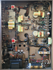
Yes, a 1.6K ohm resistor in series is ideal when replacing the selenium with a silicon rectifier (I use a Fairchild UF4007). I replace the dual filter cap in the bias supply as well. NOS axial 30D Spragues, look nice and maintain the original look . Below is a picture of my most recent 8B, which I keep as a backup amplifier.

20190729_220751.jpg
 
Last edited:
Yes, a 1.6K ohm resistor in series is ideal when replacing the selenium with a silicon rectifier (I use a Fairchild UF4007). I replace the dual filter cap in the bias supply as well. NOS axial 30D Spragues, look nice and maintain the original look . Below is a picture of my most recent 8B, which I keep as a backup amplifier.

View attachment 2095487


Crooner, your Marantz restorations and practical tips are an inspiration. My Marantz 7 is next in line to get yours and Yazaki-sans best treatments!
 
The 8B has 2x 100mA idle loading from the output stages, based on the service manual. PSUD2 indicates the power transformer secondary winding is circa 200Vrms (a series resistance measurement of the winding would be needed to get a better estimate). For an idle condition that means the HV diodes are conducting about 550mArms, and experience a PIV of about 550V. That level of current (just for idle) is imho too much for a 1N4007/UF4007, given typical diode thermal deratings that would be used. That level of PIV indicates a single 1kV PIV diode is adequate, given typical deratings for mains voltage and the doubler configuration. I would recommend a single UF5408 to replace each pair of original 35-1035 diodes (which I cannot find an OEM part number for).

The use of something like a STTH6112TV2 seems like audiophoolery to me. If there was a concern about rectification noise then make sure the ground/0V connection goes to the C20 negative terminal, and not the diode terminal, and similarly the choke connection should go directly to the C18 positive terminal, and not the diode terminal. If there was a big concern about rectification noise then determine a C-RC snubber (that requires some diy skill) across the 200Vac winding that dampens any possible glitch.
 
Last edited:
make sure you save the selinium rectifier. If you ever sell the amp, the new owner may want it. If you are interested in maintaining the value, I would not go too crazy with mods to the 8B.Once they are modd'ed their market value is greatly reduced.
 
I found replacing the selenium rectifier in the heater circuit notable produced less noise and an improved sound and soundstage.

I believe for good audio, in a circuit without a choke, the run of the mill replacement with 1N400X is an unnecessarily cheap and insufficient choice, given the subsequent advances in rectifiers.

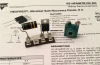
Indeed I had considered, as is recommended above by member McgJohn, the UF5408; Vishay’s ultrafast soft recovery rectifier. I had ordered several to have on hand. However, I rather used the Vishay Hexfred VS-HFA06TB120-M3 with ultrafast and ultrasoft recovery. The heater circuit does not have a choke, so it seemed to me worth erroring on the side of best not producing noise. The modern form factor of the VS-HFA06TB120-M3 tucks away on the side of the chassis and is not noticeable, except for its clarity of sound.

I used a pair of the same Hexfreds to replace the HV PSU, and again there was additional clarity and improved imaging of the sound-stage, albeit it not as notable of a step up as there was in bypassing the selenium.

I did not do a A to B comparison of the UF5408 versus VS-HFA06TB120-M3.

Member TRobbins recommendation for replacing the original quad of diodes in the HV PSU with two UF5408s, may be to member McgJohn’s point, in better keeping to the look and feel of the original of the Marantz 8 construction, than is the VS-HFA06TB120-M3. If there is any noise difference between the UF5408 and VS-HFA06TB120-M3, it is likely small, and before the choke in the HV PSU. Thus, in the HV PSU I might switch out the VS-HFA06TB120-M3 for two UF5408s so as to recapture some of the legacy look.

I am primarily interested in maximizing the sound quality. That said, further to member McgJohn’s point, I was mildly disappointed that the AudioCaps’ bright yellow detracts from the legacy look. Albeit the recap was needed, and the AudioCap Theta's are generally considered a quality film and foil capacitor for audio.
– Suggestions?
 
Last edited:
@junkscience would suggest you look into the Jupiter copper foil caps, they are the best sounding caps except the dueland coppers...
I have used these now in several amps. Great sounding cap, very organic and natural sounding.

Mcgjohn, thank you for this suggestion. Indeed I have been considering Jupiters. I wrote to Chris Young asking about Jupiters versus the Arizona Cactus that Yazaki-san recommends in his Marantz 7 rebuild, -- as Jupiter Condenser carries both. I am in Tucson Arizona where the cactus are manufactured, so they initially seemed intriguing, but I will decide on best sound basis, not regional favoritism. Subsequently I have been contemplating the Jupiters.
 
Then too, an article by Jon L in Enjoy the Music.com, he mentions that:

"I tried bypassing the AudioCap Theta with FT-1 Russian Teflon's 1/10th its value. ... I ran them for some time, and like magic, everything fell into place. The combination was at once rich, textured, and warm, yet with intact high-frequency leading edge detail and sparkle. This casserole of sorts yielded very, very satisfying results, ... In fact, to check my own impressions, I put back one of my expensive Teflon references; and I honestly can't tell you I definitely prefer the Teflons. The Teflons still have a smidge more see-through transparency and smoother liquidity, but the Theta/Teflon combo has more weight and texture behind the notes while not giving up overall resolution and punch. This combo is a definite contender in the right system."

Now I wouldn't start a restoration/refurb by installing a Theta/Teflon combination. But as the AudioCap Theta are already in my circuit, its tempting to make the easy bypass with the Russian teflon to see how this combo sounds. That before any replacement.
 
Back
Top Bottom