• The move to the new server is done. There are some software and database maintenance updates in process. This has us passing the hat around to help out. We appreciate any donations. Seriously, even a dollar helps. The payment page may be found here - https://www.audiokarma.org/support.html

Questions about UTC Williamson Schematic

zackthedog

AK Subscriber
Subscriber
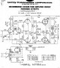
Pic attached. I'm curious about what the various compensation networks do. In addition to the shelf network across the input stage, there's a 500pF cap across the input stage cathode resistor, and networks from the output tube plates to ground. I assume these are for stabilization but wondered if anyone could explain what these things are accomplishing.

61DDD4E3-AF45-43D2-834E-4F428CF3F2F7.jpeg
 
Register to hide this ad
And there's the increased grid stopper value into the input stage as well. Would be hard to know exactly what each network is doing without having an example to measure and work with, other than their presence (or need) usually does not put a shinning light on the OPT -- or maybe it does depending on how you look at it. Normally primary snubbers are only required when ringing is serious, while shunting some of the HF NFB signal to ground at the input cathode could be to counteract the snubbers or work in conjunction with Cfb, to at least maintain a flat response in the audio band, while really curtailing things above it. Although.......being down only 1 db at 100 kHz is hardly curtailed, and could spell trouble for any significant capacitive loads. It just all depends on how well the OPT performs when wrapped with 20 db of NFB.

Dave

 
And there's the increased grid stopper value into the input stage as well. Would be hard to know exactly what each network is doing without having an example to measure and work with, other than their presence (or need) usually does not put a shinning light on the OPT -- or maybe it does depending on how you look at it. Normally primary snubbers are only required when ringing is serious, while shunting some of the HF NFB signal to ground at the input cathode could be to counteract the snubbers or work in conjunction with Cfb, to at least maintain a flat response in the audio band, while really curtailing things above it. Although.......being down only 1 db at 100 kHz is hardly curtailed, and could spell trouble for any significant capacitive loads. It just all depends on how well the OPT performs when wrapped with 20 db of NFB.

Dave

Thanks, Dave. That cap across the cathode resistor now makes sense.

I have some UTC LS-57's on the way. Never had a UTC before, I'm interested to see what they look like on the 'scope.
 
The best Williamson transformers I ever saw were the Peerless units supplied with Heath's W-2 amplifiers. Having 50% screen taps and a 10 KΩ primary impedance (as I recall), they aren't technically UL transformers -- but the transient stability they provided on any output configuration was unmatched in my opinion -- although it required a different FB network for each output impedance configured offered.

Dave
 
The best Williamson transformers I ever saw were the Peerless units supplied with Heath's W-2 amplifiers. Having 50% screen taps and a 10 KΩ primary impedance (as I recall), they aren't technically UL transformers -- but the transient stability they provided on any output configuration was unmatched in my opinion -- although it required a different FB network for each output impedance configured offered.

Dave

Yup, got a pair here. I'm currently using the S-265-Q's, and I recently built a pair of monoblocks for a friend using the Heyboer copies. All three are very easy to work with for an amateur. ;-) Very smooth HF response. Any ringing is easily tamed.
 
Thanks for bringing up the UTC circuit. I hadn't noticed that the 1962 UTC catalog included a variety of 'PA' amps (p.19) all based on the Williamson circuit, with a variety of tweaks to suit the OPT chosen, and achieving a variety of 1W bandwidths (out to 100kHz). Was that schematic page from https://www.ampslab.com/vintage1.htm ?

It looks like the mid-band feedback is circa 15dB, as the table shows Rfb=6k8 for 8 ohm tap, rather than 3k5 for Williamson amp.

The 50k input stopper may not impose itself too much on the 100kHz bandwidth, as the miller effect multiplier may be quite low by that frequency.

A nice aspect of that UTC catalog (p.23) is that they provide filter choke inductance data for 4 DCmA settings, although they don't state the test ACV.

Ciao, Tim
 
The schematics were from Oestex.com but you can find them in any UTC transformer catalog c. 1960. The HA-136 is 6.6K p-p with 43% screen taps. I'm on the lookout for those. ;-)
 
I've checked with Dennis and he doesn't recall where the 20W to 50W UTC amp schematics came from. Those schematics are in the 1960 UTC catalog onwards, but not the 1956 catalog. I might get a lead on the 1958 UTC catalog, but if anyone has a UTC catalog from 1957, 58 or 59 I'd appreciate a chance to check if those schematics are in any of those catalogs. The schematics cover 20, 25, 35, 50 and 60W amps, and using UTC output transformers HA-136, CG-20, LS-35, CG-21, and LS-65 respectively. The Linear Standard 'LS' range were associated with Williamson application in the early 1950's (eg. LS63). CG stands for commercial grade range, and HA for Hypermalloy (supermalloy) range.

I can see the benefit for UTC to propose schematics that use a range of their output transformers, and have been designed to be stable (one assumes).
 
Back
Top Bottom