• The move to the new server is done. There are some software and database maintenance updates in process. This has us passing the hat around to help out. We appreciate any donations. Seriously, even a dollar helps. The payment page may be found here - https://www.audiokarma.org/support.html

Questions on Winding Crossover Inductors

AA6U

Active Member
Normally I would never consider winding crossover inductors, but someone wants me to build them two JBL N2600 crossovers almost from scratch. Someone had gutted the original crossovers and left only the box, switches and pots. Fortunately, it's a relatively simple crossover with few components. The capacitors were not a problem. The inductors are.

Each crossover needs a 1.4 mH inductor tapped at .7 mH. I bought a 1.5mH iron core inductor (18 gage wire) from Parts Express (air inductors are too big for the set up and cost too much for the speaker owner). I then used a B&K 879B LCR meter as a guide to remove windings to bring it to 1.4 mH.

I then needed to create the center tap, so I had to unwind all of the wire and add a tap halfway along the wire. I then wound it back on the iron core but found the inductance had decreased from 1.4 mH to 1.18 mH. Note that I could not wind the wire back as neatly or tightly as the original winding so that probably explains the lower inductance.

In measuring the center tap after winding the inductor, I found one side measures 360 uH and the other measures 250 uH which only add up to 610 uH, about half of the 1.18 mH total measurement from end to end of the entire inductor. I found that the lower value section was the outer windings, which makes sense, but I am confused as to why the two do not add up to 1.18 mH, the total measured for the inductor. Note that I rechecked the measurements on a Sencore "Z Meter" and they were close to the B&K measurements.

Does anyone have any guidance for me in winding these coils with a correct center tap other than by trial and error and also explain why the sum of the two half measurements do not equal the whole?
 
Register to hide this ad
So, why not just get two 0.7 mH chokes, wire them in series, and take the tap between them? Just don't "stack" the two 0.7s so that their inductance goes above 1.4 mH.

The reason the two measurements do not equal the whole is because the inductance increases at a non-linear rate with the number of turns.

I have three 2 mH air core inductors "stacked" for my woofer. I placed the three coils on a common spindle to get them perfectly aligned then hot glued them together.

The first tap (where the first two coils are soldered together) shows 2 mH. The second tap (where the second and third coils come together), shows 5 mH. The final tap (after the third coil) shows 8 mH.

Had I not "stacked" the coils (i.e., separated them), the taps would have been 2, 4, and 6 mH.
 
Last edited:
Great idea! I only have one core for each crossover, but I could wind each .7 mH section separately next to each other (not overlap) and tap them in the middle.
 
Last edited:
Great idea! I only have one core, but I could wind them separately next to each other (not overlap) and tap them in the middle.

Keep the two sides "spaced apart" or in "different planes" so they do not add up to more than 1.4 mH.
 
So, why not just get two 0.7 mH chokes, wire them in series, and take the tap between them? Just don't "stack" the two 0.7s so that their inductance goes above 1.4 mH.

The reason the two measurements do not equal the whole is because the inductance increases at a non-linear rate with the number of turns.

I have three 2 mH air core inductors "stacked" for my woofer. I placed the three coils on a common spindle to get them perfectly aligned then hot glued them together.

The first tap (where the first two coils are soldered together) shows 2 mH. The second tap (where the second and third coils come together), shows 5 mH. The final tap (after the third coil) shows 8 mH.

Had I not "stacked" the coils (i.e., separated them), the taps would have been 2, 4, and 6 mH.

I would just add to orientate the coils in different directions so that they do not influence each other, as (I assume) they could be mounted fairly close to each other.
 
If both taps are used at the same time in the circuit then you need them to have mutual coupling.
Please post the schematic or a link to one.
What I would have done is to unwind and use an exacto knife edge to make a connection into the
wire at the guess of a tap point, continue to test until you find the correct point, then unwind only as
much as is needed. Bring the tap straight up and out do not lay it down. Then wind it back and measure up to the 1.4 mH.
 
Last edited:
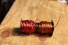
I unwound it and then wound two separate .7 mH coils side by side on the same iron core and connected them in series (see photo). Each measures almost exactly .7 mH by itself, but the series inductance of the two is 2 mH, not 1.4 mH as needed or expected.

I've also included the schematic.
 

Attachments

  • IMG_5362.JPG
    IMG_5362.JPG
    70.4 KB · Views: 33
  • N2600.pdf
    N2600.pdf
    55.9 KB · Views: 10
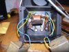
I also found this photo of an original JBL N2600 crossover showing the original inductor.
 

Attachments

  • Original N2600 Crossover.jpg
    Original N2600 Crossover.jpg
    105.2 KB · Views: 37
I unwound it and then wound two separate .7 mH coils side by side on the same iron core and connected them in series (see photo). Each measures almost exactly .7 mH by itself, but the series inductance of the two is 2 mH, not 1.4 mH as needed or expected.

I've also included the schematic.

You need to get them off of the common core and further apart and/or in different planes. But at this point, you can simply unwind one side a bit so that the total at the two outter ends is 1.4 mH. Obviously you have a way to measure this.

The start point of the fully wound side to the what is now center tap, should not change, but varify this.
 
To separate them would require sawing the iron core in half with a hacksaw which doesn't look like fun unless the iron is softer than it looks. I can easily unwind wire from each coil to bring the total series inductance to 1.4 mH, but then each section will be less than .7 mH. Is that critical?
 
No. Put your meter across the combined section and unwind wire from just one section until it reads 1.4mH.

The section that you left alone should still be 0.7 mH. Even the JBL schematic shows this and how it is to be wired.

BTW, you are probably approaching this wrong and making more work for yourself and using more parts than necessary.

The crossover is designed to be able to switch between a 16 ohm and 32 ohm load so it could be used with different impedience components of the day.

If you know what speakers are being used and you know their impedience, why not just make the crossover to work with that load???

For example, for a 16 ohm load you would use 0.7 mH and don't need the 1.4 mH. And, you would only use one 3 mfd cap. And, you no longer need the switch, which is prone to electrical noise/failure over time.

http://www.jblproservice.com/pdf/Network Schematics/N2600.pdf
 
Last edited:
Here is the issue, when you wind two .7 mH inductors on a common core there
is mutual coupling boosting the total inductance. Your first .7 mH is fine, now
just wind down the additional inductor until the total measures 1.4 mH and you
are done. You save some wire this way.
 
Got it. Looking at the illustration of the inductor in the JBL schematic, that makes sense.

Thanks so much for the great advice and insight, and I hope this will serve as a guide to other crossover construction newbies in the future.
 
Back
Top Bottom