• The move to the new server is done. There are some software and database maintenance updates in process. This has us passing the hat around to help out. We appreciate any donations. Seriously, even a dollar helps. The payment page may be found here - https://www.audiokarma.org/support.html

QX-949 repair

Anonky

Kenwood KR-9600 / Pioneer SX-950 / Sony STR-GX10ES
Long story short I have a pioneer qx-949 with a weak right channel in stereo mode on AM/FM/phono inputs; there is essentially no bass output and treble sounds off too in the weak channel. AUX input works perfectly in stereo mode (no weak channel). To make things more interesting, when I flip the receiver to RM quad mode, the right channel works fine on all inputs. I’ve cleaned all contacts several times and I’m now in search of a cold joint somewhere or looking for a problematic cap. These brutes are packed tight.

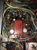
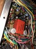
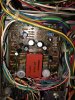
Considering this issue, I’ve found that the aux input bypasses the equalizer amplifier, which presumably is where the problem lies (please correct me if this logic might be flawed). On visual inspect of the eq amp board components, nothing looks visually out of whack on top. With the unit turned on and probing the components with the eraser end of a pencil (safety first) does not cause any change in the weak channel. I want to take the board out and inspect the joints themselves on the back OR simply to recap this entire board. Either situation I will have to remove this board, but I’m having trouble figuring out how to remove the board from the unit. There are several wires seemingly keeping it in place and I’m not sure if it is able to be easily removed. This will be my first real repair that required anything outside of just deoxing controls so I apologize if this is a rudimentary question. Below are pics of the board in question. Appreciate any help or advice!
 

Attachments
  • 04E5B738-0081-487D-ADE8-A0B8AB3D5AF5.jpeg
    04E5B738-0081-487D-ADE8-A0B8AB3D5AF5.jpeg
    152.5 KB · Views: 32
  • 2A65F44B-7C25-48CF-AC0E-E23D8AD0AAF9.jpeg
    2A65F44B-7C25-48CF-AC0E-E23D8AD0AAF9.jpeg
    191 KB · Views: 29
  • 9FF6B83A-AE43-4EEC-87C5-1B208CA8CDB4.jpeg
    9FF6B83A-AE43-4EEC-87C5-1B208CA8CDB4.jpeg
    156.7 KB · Views: 28
Last edited:
Register to hide this ad
i rebuilt one of those 3 yrs ago, they are a real pain to do. there were several boards i had to remove WIRES to access the foil side of the board . i did not however remove the entire board anywhere. just enough to gain access and honestly. i dont remember if that board was one of them. all i can tell you is to free the harness from the nylon harness clips and try to get as much slack as you can. and there isnt a lot of slack to be had on any board in that set. i recapped the thing in its entirety and replaced all the transistors that were known trouble makers. it was a real burnout i dont want to repeat. you would be well advised to check what transistors are on that board and dont rely on the manual data sheet. pioneer used 2sa763 and 2sa725 interchangeably and whats in the set is important as the '725 is a KNOWN catastrophic failure item its replaced with ksa992. same goes for the 2sc1327 that was also a 2sc1312. the 1312;s get noisy. the 1312's are replaced with ksc1845. ive read that the 763 was not failure prone and i dont know about the 1327. considering the grief in doing anything on that set my inclination would be to rebuild that board and replace all the silica and caps and be done with it. but thats just me.
 
Last edited:
Long story short I have a pioneer qx-949 with a weak right channel in stereo mode on AM/FM/phono inputs; there is essentially no bass output and treble sounds off too in the weak channel. AUX input works perfectly in stereo mode (no weak channel). To make things more interesting, when I flip the receiver to RM quad mode, the right channel works fine on all inputs. I’ve cleaned all contacts several times and I’m now in search of a cold joint somewhere or looking for a problematic cap. These brutes are packed tight.

Considering this issue, I’ve found that the aux input bypasses the equalizer amplifier, which presumably is where the problem lies (please correct me if this logic might be flawed). On visual inspect of the eq amp board components, nothing looks visually out of whack on top. With the unit turned on and probing the components with the eraser end of a pencil (safety first) does not cause any change in the weak channel. I want to take the board out and inspect the joints themselves on the back OR simply to recap this entire board. Either situation I will have to remove this board, but I’m having trouble figuring out how to remove the board from the unit. There are several wires seemingly keeping it in place and I’m not sure if it is able to be easily removed. This will be my first real repair that required anything outside of just deoxing controls so I apologize if this is a rudimentary question. Below are pics of the board in question. Appreciate any help or advice!

Considering this is your first component/part level repair...or if it wasn't... you might diagnose the problem to at least the board level before you start changing things. It's too easy to create a problem with a simple mistake compounding trouble shooting if it should become necessary. Those are fairly complex units and not the easiest to work on. I'm not dissuading you at servicing the unit simply giving advice based on years of servicing electronic equipment. Those are very attractive and good sounding units, if I had one I'd service and use it. Get the schematic and study it for signal flow, ask questions, it might be diagnosed to the board by symptoms considering the bad channel works in certain modes. A scope would be nice, a great help, but not absolutely necessary. Take lots of pictures before you attempt to remove anything in case a wire or two break free, can save a lot of time.
 
Considering this is your first component/part level repair...or if it wasn't... you might diagnose the problem to at least the board level before you start changing things. It's too easy to create a problem with a simple mistake compounding trouble shooting if it should become necessary. Those are fairly complex units and not the easiest to work on. I'm not dissuading you at servicing the unit simply giving advice based on years of servicing electronic equipment. Those are very attractive and good sounding units, if I had one I'd service and use it. Get the schematic and study it for signal flow, ask questions, it might be diagnosed to the board by symptoms considering the bad channel works in certain modes. A scope would be nice, a great help, but not absolutely necessary. Take lots of pictures before you attempt to remove anything in case a wire or two break free, can save a lot of time.
I’m pretty determined to fix this. If not myself, I at least want to troubleshoot exactly where the issue as narrowly as possible so I can take it to a tech and request they replace specifically xyz components so as to keep the bill under control and hopefully just repairing that one entire board (or less) will fix my problem. I do have an oscope but I’ve yet to use it for any troubleshooting. This may be its time to shine. Any good resource to learn how to use them in this capacity?

Regarding john stumpf’s reply, I will look at that board here shortly. Gotta brew a pot of coffee then I’ll get to it. Will reply back with updates.
 
@john stumpf and @spicer
So I'm kind of in the same predicament. Not really sure how to get this board out of the unit which houses all of the eq amp components as well as the LPF @john stumpf mentioned. I'm not finding a way to easily move around wires to make things easier. If I were to take this in for a repair and the issue were hypothetically isolated to units on this eq board and they replaced everything or even just the problematic component, what kind of cost would I be looking at approximately? UGH. Thanks for the advice.
 
@john stumpf and @spicer
So I'm kind of in the same predicament. Not really sure how to get this board out of the unit which houses all of the eq amp components as well as the LPF @john stumpf mentioned. I'm not finding a way to easily move around wires to make things easier. If I were to take this in for a repair and the issue were hypothetically isolated to units on this eq board and they replaced everything or even just the problematic component, what kind of cost would I be looking at approximately? UGH. Thanks for the advice.

Hopefully someone here experienced with those units will guide you to diagnosing and servicing the set, you will have to do it yourself or expect to pay for a hopefully qualified tech to go through it. It is not practical, not really even possible to approach a shop under those circumstances... they need to diagnose themselves, once in it they are responsible and won't approach it any other way, that is the professional way. However... you said you have a scope... that makes everything a lot easier, for your purposes here use of the scope is very straightforward. Go to Hi Fi Engine and download the service manual... study it a while with the problem in mind... make a project of it, your probably going to have a lot of fun and personal satisfaction doing it yourself... and besides, there is a very real possibility you'll have to do it yourself. Get ready... someone is going to pick up the ball and enjoy guiding you through it, others will help too.
 
Hopefully someone here experienced with those units will guide you to diagnosing and servicing the set, you will have to do it yourself or expect to pay for a hopefully qualified tech to go through it. It is not practical, not really even possible to approach a shop under those circumstances... they need to diagnose themselves, once in it they are responsible and won't approach it any other way, that is the professional way. However... you said you have a scope... that makes everything a lot easier, for your purposes here use of the scope is very straightforward. Go to Hi Fi Engine and download the service manual... study it a while with the problem in mind... make a project of it, your probably going to have a lot of fun and personal satisfaction doing it yourself... and besides, there is a very real possibility you'll have to do it yourself. Get ready... someone is going to pick up the ball and enjoy guiding you through it, others will help too.
Yeah I called a repair shop and was told it’d likely be $300 minimum so DIY is gonna be the way to go. I’m very determined to figure this out. And I agree about the satisfaction—been restoring speakers and love the feeling when it’s finished. I have a close friend whose an electrical engineer and into this sort of stuff too so between the two of us and a bit of guidance I’m optimistic!
 
Last edited:
believe it or not i broke a wire on my 949 rebuild and lost a channel. i used a multimeter on the millivolt scale to find it. radio audio out is about 100 mv ac. the fm radio was the signal. , even interstation noise will work i imagine. input on the equalizer is 4-7 (left and right) it would seem plausible that if millivolts are low on the output,14 0r 17 (but not both) and are equal on the input at least you know its that board. i am an electrician by training. or you could use a scope. as far as that band pass filter goes its still a possibility. but as spicer noted you need to at least reduce this to a board. that filter can only be had off another used board and you wont find one new. it was used in other pioneer boards as well. neither will any shop as far as that goes, the 016 filter ive read here is potted and to get at the coils and caps you have to mine it out the 019 will replace it and is not potted. but a bad transistor could also be the trouble i should think. make sure you insulate the probe so you dont short between the pins or use mini grabbers. it costs 0 $ to do this. there are more sophisticated ways of approaching this thats certain but a low output at the speaker is a low INPUT somewhere, lots of switches in those things too.
 
Last edited:
in case you need a bandpass they were used on the 939 and 1010 tuner boards and probably others. someone wrote here many moons ago he was going to try one from a sx850 a different number,but like some other posts there was never any follow up on how or if it worked out. there used to be a lot of boards on ebay but not so much any more.
 
in case you need a bandpass they were used on the 939 and 1010 tuner boards and probably others. someone wrote here many moons ago he was going to try one from a sx850 a different number,but like some other posts there was never any follow up on how or if it worked out. there used to be a lot of boards on ebay but not so much any more.
I won’t let this thread go cold. I’ll update you!
 
believe it or not i broke a wire on my 949 rebuild and lost a channel. i used a multimeter on the millivolt scale to find it. radio audio out is about 100 mv ac. the fm radio was the signal. , even interstation noise will work i imagine. input on the equalizer is 4-7 (left and right) it would seem plausible that if millivolts are low on the output,14 0r 17 (but not both) and are equal on the input at least you know its that board. i am an electrician by training. or you could use a scope. as far as that band pass filter goes its still a possibility. but as spicer noted you need to at least reduce this to a board. that filter can only be had off another used board and you wont find one new. it was used in other pioneer boards as well. neither will any shop as far as that goes, the 016 filter ive read here is potted and to get at the coils and caps you have to mine it out the 019 will replace it and is not potted. but a bad transistor could also be the trouble i should think. make sure you insulate the probe so you dont short between the pins or use mini grabbers. it costs 0 $ to do this. there are more sophisticated ways of approaching this thats certain but a low output at the speaker is a low INPUT somewhere, lots of switches in those things too.
Ok finally got an update (on Unit A to be clear). On the eq amp board when playing FM on a station I’m getting the following measurements from the EQ amp board.
Pins 4-7 all stable at 1.0 mV.
Output pin 14 oscillating between 0.5mV to 3.6mV. 15-17 all stable at 1.6mV

Thoughts?
 
Last edited:
@john stumpf ? Sorry to pester. Just need guidance. I think I’m going to just start by replacing the 4 caps that lead from the input on this eq amp board to pin 14 where I’m getting a strange reading and see if that fixes it. If not that move to the transistors on that channel next. Think that’s a reasonable plan?
 
Any guidance appreciate.. anyone. If no responses going to just replace all caps and transistors on that channel side of the board. Would be less than 10 components. Someone stop me if I’m mouth breathing
 
Back
Top Bottom