• The move to the new server is done. There are some software and database maintenance updates in process. This has us passing the hat around to help out. We appreciate any donations. Seriously, even a dollar helps. The payment page may be found here - https://www.audiokarma.org/support.html

QX8000A FM Tuner Right Side weak and noisy. Help?

jd3rdcoast

Super Member
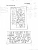
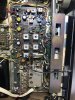
I could use some help troubleshooting this FM Tuner problem on this nice Quad unit. Previously repaired the Main Amp boards. Cleaned all controls with CRC contact cleanser and CRC2-26 lube. AUX inputs all working fine on all 4 channels. But in FM mode the right channel is much lower than right and noisy. I thought I had it isolated to the Head Amp board because the input side seemed OK on both channels viewing with a scope but and the outputs showed Rt side much reduced waveform then left when viewed with scope. I wound up replacing all 2SC1344’s with KSC1845’s and recapped it. Couple caps out of spec and C7 0.47 was actually bad on Left Side. No change of problem. Getting good 25v to Head Amp

Mono mode is quieter with less bass but still the distortion/noise. Auto mode which I assume kicks in the MPX circuit is much more amplified and w bass but distortion as well. Again Left Side is beautiful.

Unfortunately this is my first attempt at Dx an FM board. Any suggestions where to start would be helpful.
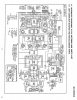
C403DE2B-EE3B-459B-BBFE-A66B1288402B.jpeg 0904C1FE-D20F-4D90-8652-D2D81958FDA0.jpeg 98A2AEE7-C14E-4F5F-81E5-8552EC875A30.jpeg E2BEC5F5-8AFB-48F2-B3AC-FF04E32F9819.jpeg
 
Last edited:
Register to hide this ad
...But in FM mode the right channel is much lower than right and noisy.

I'm guessing by the context of the rest of your message that the passage should have read " right channel is much lower than LEFT" but I can't be certain.

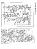
There is a section in the manual showing a channel balance control on the CR board (AWX-004) which seems to affect the L/R balance out of the FM tuner section only. It looks like VR1 on the diagram, and it appears to be an R/C network intended to attenuate some signal on the right channel. This might bear investigation. That e-cap in the circuit could be damaged.
 
A few of these old FM tuners in these threads of late.
It is hard to compare FM L/R channel level balance using music as your source. Maybe noise would be better as a means of comparing levels. Obviously having proper test equipment (mpx rf sg) would help but it is expensive.
Use the tape record o/p's into your 2ch scope as a measurement point.
Mono mode is quieter with less bass but still the distortion/noise. Auto mode which I assume kicks in the MPX circuit is much more amplified and w bass but distortion as well. Again Left Side is beautiful.
Could be a dirty de-emphasis switch S6. Should be set to 75uS.
 
I'm guessing by the context of the rest of your message that the passage should have read " right channel is much lower than LEFT" but I can't be certain.

There is a section in the manual showing a channel balance control on the CR board (AWX-004) which seems to affect the L/R balance out of the FM tuner section only. It looks like VR1 on the diagram, and it appears to be an R/C network intended to attenuate some signal on the right channel. This might bear investigation. That e-cap in the circuit could be damaged.
That is correct. Right channel much less output then Left in FM mode with some distortion. Apologies. I will check the CR board more closely. Thanks.
I'm guessing by the context of the rest of your message that the passage should have read " right channel is much lower than LEFT" but I can't be certain.

There is a section in the manual showing a channel balance control on the CR board (AWX-004) which seems to affect the L/R balance out of the FM tuner section only. It looks like VR1 on the diagram, and it appears to be an R/C network intended to attenuate some signal on the right channel. This might bear investigation. That e-cap in the circuit could be damaged.
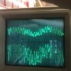
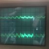
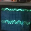
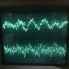
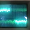
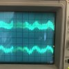
Here is couple pics of dual scope signals on the AWX-0012 CR Unit board. (this board instead of AWX-oo4). Top is Right FM Ch. bottom is Left. Getting good 12.5v to this board. Seems pretty clear reduced R ch straight off of FM Tuner Bd. Checking Cap on

Pic #1 is input from Tuner board to CR Unit AWX-012. Pin 6. (R) and Pin 4 (L).
upload_2018-5-8_22-43-24.jpeg
Pic #2 is taken at outputs Pin 7 (R) and Pin 5 (L).
upload_2018-5-8_22-42-36.jpeg
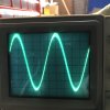
Pic #3 is @ Pin 10 (R) and Pin 11 (L) output to S1 2/5F.
upload_2018-5-8_22-42-58.jpeg
 
What do you have AWE-003 or AWE-012?
Scope/monitor pin 2,3. switch between auto and mono FM mode, lets see what the difference is.
 
A few of these old FM tuners in these threads of late.
It is hard to compare FM L/R channel level balance using music as your source. Maybe noise would be better as a means of comparing levels. Obviously having proper test equipment (mpx rf sg) would help but it is expensive.
Use the tape record o/p's into your 2ch scope as a measurement point.

Could be a dirty de-emphasis switch S6. Should be set to 75uS.
Unfortunately No Deemphasis switch on the 120v version.
 
What do you have AWE-003 or AWE-012?
Scope/monitor pin 2,3. switch between auto and mono FM mode, lets see what the difference is.
AWX-012 A is the board for 120v units.
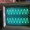
When switch to Auto you get more volume out of right channel and more equal amplitude waveform, but also much more distortion. Like a transistor is being overdriven. I’ll have to pick it up again tomorrow. Getting late.
Pic 4 of FM Auto mode.pin 2, 3 of FM Tuner board.
upload_2018-5-9_0-0-31.jpeg
 
Last edited:
AWX-012 A is the board for 120v units.
When switch to Auto you get more volume out of right channel and more equal amplitude waveform, but also much more distortion. Like a transistor is being overdriven. I’ll have to pick it up again tomorrow. Getting late.
Pic 4 of FM Auto mode.pin 2, 3 of FM Tuner board.
View attachment 1182770

Sorry crs16, I thought you asked about the CR Unit board. My Tuner Board is the AWE-003 B version. My bad, was late and brain was done.

I’m back at it today trying to trace the signal through the board. Just not sure what I’m looking for. Where exactly does the FM signal split to Left and Right so I can compare?
 
Sorry crs16, I thought you asked about the CR Unit board. My Tuner Board is the AWE-003 B version. My bad, was late and brain was done.

I’m back at it today trying to trace the signal through the board. Just not sure what I’m looking for. Where exactly does the FM signal split to Left and Right so I can compare?
In MONO mode This is the output of T15 pins 4, 6 prior to switching diodes D13-D16. The diodes seemed OK when tested with DMM diode tester.
upload_2018-5-9_13-32-23.jpeg

This is the same signal in FM AUTO mode. Scope stt at 2us/Div and 5 V, AC, trigger sync’d.
upload_2018-5-9_13-38-14.jpeg
 
Last edited:
In MONO mode This is the output of T15 pins 4, 6 prior to switching diodes D13-D16. The diodes seemed OK when tested with DMM diode tester.
View attachment 1183080

This is the same signal in FM AUTO mode. Scope stt at 2us/Div and 5 V, AC, trigger sync’d.
View attachment 1183081

Here is signals FM AUTO just before final T16, T17 on R80, R81. Scope @ .5V/div, 0.1sec/div. Can see the noise in FM signal on R side compared to L.
upload_2018-5-9_14-3-44.jpeg

Below same points in FM MONO mode. Can see the reduced amplitude of top R channel.
upload_2018-5-9_14-3-24.jpeg
 
Did you adjust T13,14,5 for max 19KHz pilot at TP2 as said in the manual?
No I did not. Can I measure (verify) that signal with my scope? Is it going to be a sine wave? Please excuse my lack of experience on certain tasks Newbie on FM Tuner.
 
That could be tough, since it normally requires a "dead air" RF and pilot signal with no audio program so the 19KHz can be measured cleanly.
 
That could be tough, since it normally requires a "dead air" RF and pilot signal with no audio program so the 19KHz can be measured cleanly.
When I look at TP2 with my scope in FM AUTO mode I get this. Scope @ 2v/div, AC, 5us/Div.
About 10vpp.
upload_2018-5-9_20-37-43.jpeg

manual says “ adjust until the output level of the 19 KHz becomes maximum on the scope”. But I’m a little nervous to start tweaking the Coils. I can mark their positions and see if can get any more signal amplitude.
 
Document all the positions, and if you are willing to risk a shop visit for alignment if it goes badly, try peaking that signal.
 
I am about as experienced with this design as you are. That is the 38KHz, which is the double of 19Khz, this is the switching frequency.
Sure mark the positions and give it a try.
 
Last edited:
When I look at TP2 with my scope in FM AUTO mode I get this. Scope @ 2v/div, AC, 5us/Div.
About 10vpp.
View attachment 1183395

manual says “ adjust until the output level of the 19 KHz becomes maximum on the scope”. But I’m a little nervous to start tweaking the Coils. I can mark their positions and see if can get any more signal amplitude.
Was able to adjust waveform at TP2 from 10vpp up to about 14vpp on scope using T13 & T15. T14 is not have much affect. But this did not resolve any of my issue. FYI, earlier I had cleaned the FM Mute switch again because I had noticed if I pushed it at just the right spot could get some clicks and distortion. Cleaned as good as possible. Improved the contacts but no change in initial problem.
upload_2018-5-9_21-22-43.jpeg
 
I am not sure if I can help you much further, since I have no experience with this ckt and do not have one of my own to compare against.
I think you need to send in a composite sig from a proper mpx generator to sort out what is going on. Need to independently provide a L & R.
BTW I use a later model HP 8904A with opt 001,002
The service manual is sort of weak, like they say to adjust for a maximum 19KHz and you are seeing 38KHz which is weird.
Dr*Audio or PunkerX in the tuner forum could be of more help, worth a try, since they have more experience than I. Ask PunkerX (Mike) to transfer this thread to the tuner forum, if possible.

Good Luck
Rick
 
Last edited:
I am not sure if I can help you much further, since I have no experience with this ckt and do not have one of my own to compare against.
I think you need to send in a composite sig from a proper mpx generator to sort out what is going on. Need to independently provide a L & R.
BTW I use a later model HP 8904A with opt 001,002
The service manual is sort of weak, like they say to adjust for a maximum 19KHz and you are seeing 38KHz which is weird.
Dr*Audio or PunkerX in the tuner forum could be of more help, worth a try, since they have more experience than I. Ask PunkerX (Mike) to transfer this thread to the tuner forum, if possible.

Good Luck
Rick
Thanks, will do. I was just searching the Tuner Forum and nothing there for my model, but I’m sure will get some support or direction if can’t go any further with my equipment and skills. Thanks for trying.
 
Back
Top Bottom