
• The move to the new server is done. There are some software and database maintenance updates in process. This has us passing the hat around to help out. We appreciate any donations. Seriously, even a dollar helps. The payment page may be found here - https://www.audiokarma.org/support.html

RCA Console Stereo has loud "Hummmming" Noise

Note that you have two 100mfd 200 W.V. capacitors under the chassis -- the large brown cans held in place with metal straps. They should be replaced too.
View attachment 1311692

In regards to the brown capacitors mentioned in this reply, they are marked with the "+" on one end. I assume that's the positive end. The new ones have only "-" for negative. This may be a stupid question, but should I put the new ones in with the negative leads where the old ones had the positive leads?

The reason I ask is I completed the work this evening. I installed the power board back in, right when I turned the until on, it blew the fuse. The only thing I can think of is those caps are wired in backwards. I could definitely be wrong, but not sure what else it could be.
 
Also, according to the link provided for restuffing capacitors, the negative leads went to the terminals and the positive leads we're tied together and put to ground. Does that sound correct?
 
In regards to the brown capacitors mentioned in this reply, they are marked with the "+" on one end. I assume that's the positive end. The new ones have only "-" for negative. This may be a stupid question, but should I put the new ones in with the negative leads where the old ones had the positive leads?
No. Negative should go to negative.
The reason I ask is I completed the work this evening. I installed the power board back in, right when I turned the until on, it blew the fuse. The only thing I can think of is those caps are wired in backwards. I could definitely be wrong, but not sure what else it could be.
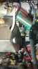
Check your wiring. It's possible you've inadvertently shorted something else, or something else has coincidentally failed, or the inrush current with the new caps is just that much higher that it kills the fuse (this is unlikely, though), or one of the new caps is shorted.
 
Also, according to the link provided for restuffing capacitors, the negative leads went to the terminals and the positive leads we're tied together and put to ground. Does that sound correct?
That sounds incorrect. Multi-cap cans normally have a negative can and positive terminals. But check the circuit diagram or the circuit itself to see if this is a cap that -- very unusually, I think-- was made with a +ve can and negative terminals.
 
That sounds incorrect. Multi-cap cans normally have a negative can and positive terminals. But check the circuit diagram or the circuit itself to see if this is a cap that -- very unusually, I think-- was made with a +ve can and negative terminals.

Ok, this is where I got that from. Apparently this was for "bias cans"....I'm not familiar with the terminology. This was my first project .
 

Attachments

  • Screenshot_20181103-075044.png
    Screenshot_20181103-075044.png
    186.4 KB · Views: 13
Ok, this is where I got that from. Apparently this was for "bias cans"....I'm not familiar with the terminology. This was my first project .
I don't recognise the "bias cans" terminology either, and I don't see where a multi-cap can would be both used as part of a bias circuit and have a positive can. It strikes me as at best highly unusual; more likely it's a mistake.

Anyway, you've got a power supply filter cap, not a "bias can" (whatever that is). I've never seen a power supply multi-cap that had a positive can, but again, I suppose anything is possible. It seems overwhelmingly likely that the multi-cap in your amplifier is supposed to be negative can with positive terminals.
 
I don't recognise the "bias cans" terminology either, and I don't see where a multi-cap can would be both used as part of a bias circuit and have a positive can. It strikes me as at best highly unusual; more likely it's a mistake.

Anyway, you've got a power supply filter cap, not a "bias can" (whatever that is). I've never seen a power supply multi-cap that had a positive can, but again, I suppose anything is possible. It seems overwhelmingly likely that the multi-cap in your amplifier is supposed to be negative can with positive terminals.

Ok, so I have likely wired it up backwards then. I will see if I can find the wiring diagram to confirm. Thank you.
 
I don't recognise the "bias cans" terminology either, and I don't see where a multi-cap can would be both used as part of a bias circuit and have a positive can. It strikes me as at best highly unusual; more likely it's a mistake.

Anyway, you've got a power supply filter cap, not a "bias can" (whatever that is). I've never seen a power supply multi-cap that had a positive can, but again, I suppose anything is possible. It seems overwhelmingly likely that the multi-cap in your amplifier is supposed to be negative can with positive terminals.


You were absolutely correct! Flipped the direction of the new capacitors and now it's working perfectly! Saved a really nice old console stereo!

Thanks for all of your help! Greatly appreciated, sir.
 
3.9k ohm 10% tolerance, likely about 5 watt.

They're made to get hot, and solder heat is unlikely to have damaged them. Resistors do sometimes drift in value, though. Measure them with an ohmmeter and see if they're still within 10% of 3.9k ohm.

If it were me I wouldn't have bothered unsoldering; just snipped close to the joint and soldered new connections.

Use this to convert resistor colour codes: https://www.digikey.com/en/resource...version-calculator-resistor-color-code-4-band

So, I am looking to do some resistors on a different project. I am curious how you know which direction to read the colors from on a resistor? For example, if the bands are Silver/Red/Black/Brown, depending on which way you input that into the resistor calculator on the link provided, that will be two very different values. How can I be sure I am reading these in the correct direction?
 
So, I am looking to do some resistors on a different project. I am curious how you know which direction to read the colors from on a resistor? For example, if the bands are Silver/Red/Black/Brown, depending on which way you input that into the resistor calculator on the link provided, that will be two very different values. How can I be sure I am reading these in the correct direction?
If it's four bands, the reading only goes one way because silver is only a valid choice in the tolerance band. Thus, you read it as brown, black, red, silver, which is a 1k ohm 10% tolerance resistor.
 
If it's four bands, the reading only goes one way because silver is only a valid choice in the tolerance band. Thus, you read it as brown, black, red, silver, which is a 1k ohm 10% tolerance resistor.

Ok, I see now. So, it's important to install the new resistors in the same way that the originals were installed, correct? As in, they are directional?

Also, one other question. There are some green axial capacitors in the amp. They have very low MFD values. What do you suggest replacing these with? The values seem to be pretty uncommon. Not sure if they are typically replaced with aluminum electrolytic axials or something different?
Values include:
0.47 MFD 600 VDC
0.10 MFD 600 VDC
10 MFD 400 VDC
0.10 MFD 400 VDC

Thanks .
 

Attachments

  • Screenshot_20181202-222935.png
    Screenshot_20181202-222935.png
    351 KB · Views: 7
Ok, I see now. So, it's important to install the new resistors in the same way that the originals were installed, correct? As in, they are directional?

Non directional.

Those (0.47uF @ 600V) capacitors are coupling capacitors and are not electrolytics. You can use all 600 volt capacitors here and just use the next step up or two in values.
 
Back
Top Bottom