• The move to the new server is done. There are some software and database maintenance updates in process. This has us passing the hat around to help out. We appreciate any donations. Seriously, even a dollar helps. The payment page may be found here - https://www.audiokarma.org/support.html

RCA RS-177A console pull refurb

hrtattckcity

AK Subscriber
Subscriber
Starting another RCA RS-177A thread--I know there are several, and I have read through many, but this is my first tube project and I want to consolidate all of my noobish questions in one place.

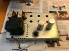
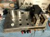
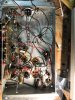
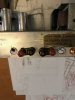
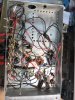
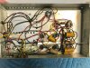
For reference, to start, photos of top and bottom and a cropped schematic of the power amp, without the preamp and tuner.

I know this unit is a bit scant on gain--but my intent is to clean up the extraneous switches and jacks, recap, and add fuse, power switch, binding posts and rca jacks keeping the schematic more or less stock before deciding if I want to add an additional gain stage or modify the existing gain stage.


-I have new .27uf Panasonics to replace the wax and paper caps, as well as the 2x 100pf (MMF) capacitors
-I have new individual electrolytics for the multi-section can caps.


A couple of questions to start:

What wattage are the resistors on the schematic, if no wattage is listed?
And/or what is a suitable replacement?

For maximum flexibility in the future, should I plan to use the 4ohm or 8ohm feeds?

What rating fuse would be sufficient? I believe someone in another thread suggested 1A slow-blow?
 

Attachments

  • chassis bottom before.jpg
    chassis bottom before.jpg
    134.7 KB · Views: 263
  • chassis top before.jpg
    chassis top before.jpg
    92.9 KB · Views: 271
  • RS-177A CROPPED.pdf
    RS-177A CROPPED.pdf
    35.2 KB · Views: 89
Register to hide this ad
If someone could review my markup of the schematic to show how to remove the 9 pin connector I would appreciate it.

(I'm doing some extrapolating from secret4mula's markup of the schematic to add the linestage back in)

-connect the wires going from position 1 to 3 (black lead to transformer and negative to outlet)
-keep the two wires going to 2 connected, but add a switch and fuse in line (positive to outlet and red-blk to transformer
-keep the brown transformer leads connected to the brown wires feeding the series of tubes at 8 & 9--but remove from 9 pin connector.
-eliminate ground wire at 6?
-eliminate single wire at 7 going from connector to 35mfd can cap?
 

Attachments

The marking convention for resistors is 1/2W unless marked otherwise. Modern resistors can be much smaller for the same power rating, and small resistors tend to have lower voltage ratings. I generally order 1W or higher-rated metal film or metal oxide film resistors to obtain similar physical size and voltage rating for this application. Carbon film types are okay for replacement. Metal film or metal oxide film offers better performance, which can sometimes make an audible improvement. The most critical location for resistor quality is in the feedback network. If you want to retain as much of the amp's original distortion characteristic as possible, then stick with the original carbon composition resistors there. Unless their values are out of tolerance, of course.
 
I'd use a 2A fast blow fuse. Output tap on secondary depends of course on the speakers you use. Why not make both output taps available?
 
Last edited:
I’m gonna follow what you do here closely. I pulled an RS 177 and it’s tuner/preamp unit from a console years ago. They are in storage. I repurposed the nice wood console into a stereo stand by refinishing and turning it on it’s end vertically. I’m also aware of the modest gain of the amp when used standalone. Why not combine the two and employ the extra gain tube found in the preamp? I’ll bet the RCA tuner is pretty good in these things. Someday I’m gonna try this (I hope).
 
If you haven't looked at Jheu02's thread (http://www.audiokarma.org/forums/index.php?threads/rca-4vf464-restoration.433025/) you should--he had the whole console including the preamp and tuner.
I, however, only have the power amp.


I’m gonna follow what you do here closely. I pulled an RS 177 and it’s tuner/preamp unit from a console years ago. They are in storage. I repurposed the nice wood console into a stereo stand by refinishing and turning it on it’s end vertically. I’m also aware of the modest gain of the amp when used standalone. Why not combine the two and employ the extra gain tube found in the preamp? I’ll bet the RCA tuner is pretty good in these things. Someday I’m gonna try this (I hope).
 
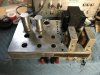
I drilled out rivets to start removing the 9 pin connector and other switches and connectors, and made holes for new jacks, binding posts, power switch and fuse holder.

Unfortunately I clumsily broke one resistor--and was tempted to replace all while I am at it;

Can anyone confirm that the values for r202 and r212 are correct on the schematic--parallel positions but different values?

r201,r211 - 470k
r202 - 470k/r212 - 56k?
r203,r213 - 2700
r204,r214 - 22k
r205,r215 - 22k
r206,r216 - 470k
r207,r217 - 470k
r208,r218 - 8200
r209,r219 - 5600
r210,r220 - 47 2w
r221,r222 - 82k
r224,r223 - 27k
r225 - 2200 2w
r226 - 1200 4w
r228 - 4700
r229,r230 - 130
r231,r232 - 390k
 
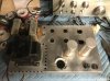
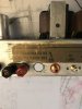
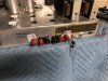
Switch and fuse holder installed on top. Rca jacks and binding posts on back.

I know this is the reverse orientation to what most people do, and don’t doubt that I’ll hear a good reason I should have done otherwise—but I was hoping to retain the area next to the 6cg7’s for a potential future added gain stage.

Per Kegger’s Rex in an earlier thread I’m replacing the brown wafer sockets with ceramics.
 

Attachments

  • C9F696D4-1955-4615-87CF-E3AE06304CDC.jpeg
    C9F696D4-1955-4615-87CF-E3AE06304CDC.jpeg
    100.5 KB · Views: 131
  • FFB78F6C-8B52-4A9F-BE84-2C2F45DAFA97.jpeg
    FFB78F6C-8B52-4A9F-BE84-2C2F45DAFA97.jpeg
    97.5 KB · Views: 127
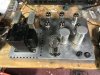
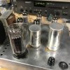
A couple of update photos. Ceramic sockets are in, slipped behind the existing. Figured I would try to move things over one at a time to not lose anything. If there is enough room to work.
 

Attachments

  • A28F235A-71CA-4994-9238-652D52B4ADDB.jpeg
    A28F235A-71CA-4994-9238-652D52B4ADDB.jpeg
    104 KB · Views: 95
Installed two terminal strips to take the place of the can caps and am in the process of moving everything over. Switch and fuse holder are wired up.
 

Attachments

  • C9B9E101-FEB6-4E2E-AFA7-EEBBB9D7D682.jpeg
    C9B9E101-FEB6-4E2E-AFA7-EEBBB9D7D682.jpeg
    85.6 KB · Views: 105
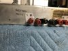
@kward made me feel lazy for not adding a second set of taps so I ordered some secondary binding posts.

I really mangled the holes for the new taps, and didn’t feel great about the imprecise clamping securing them in place inside my irregular holes, so I laser cut some small escutcheons for the 8 ohm taps with a precise hole in a piece of acrylic and two small screw holes for some 2.5mm machine screws.

Still a bit of a kludge, but feels much more stable.


I'd use a 2A fast blow fuse. Output tap on secondary depends of course on the speakers you use. Why not make both output taps available?
 

Attachments

  • 27686A83-7B7D-4392-AEF7-EDB4BFF8209F.jpeg
    27686A83-7B7D-4392-AEF7-EDB4BFF8209F.jpeg
    39.4 KB · Views: 118
  • CC83247C-6D5A-44DE-A661-3E3FF0ECEBD0.jpeg
    CC83247C-6D5A-44DE-A661-3E3FF0ECEBD0.jpeg
    119 KB · Views: 113
  • A245E5D5-83C1-4CF8-8FFF-AAC40C61A243.jpeg
    A245E5D5-83C1-4CF8-8FFF-AAC40C61A243.jpeg
    127.8 KB · Views: 111
  • BABC2608-1918-4482-A8A7-42D2B854DC34.jpeg
    BABC2608-1918-4482-A8A7-42D2B854DC34.jpeg
    38.1 KB · Views: 109
It’s all wired up, it works, it’s quiet like everyone says, but it sounds pretty good.
 

Attachments

  • A2D05D59-A61A-47B6-8677-0A23FF54FF90.jpeg
    A2D05D59-A61A-47B6-8677-0A23FF54FF90.jpeg
    83.2 KB · Views: 115
  • E23FB59E-7354-4F50-BDDD-4C79A85D4C80.jpeg
    E23FB59E-7354-4F50-BDDD-4C79A85D4C80.jpeg
    97.3 KB · Views: 113
  • 4BDBF0C5-6397-4176-8ED7-CB0E90DDFDE2.jpeg
    4BDBF0C5-6397-4176-8ED7-CB0E90DDFDE2.jpeg
    68.6 KB · Views: 110
can you post a close up shot of the input wiring? TY.

I just added extensions to the existing input wire that ran to the 3 pin connector.

Someone in one thread suggested everything be grounded in the same place it was previously to prevent hum. Not sure if there is truth to that, but it made me superstitious enough that I did it wherever I could.

I found the old ground buss extremely difficult to solder to at first. I found that if you scuff it a little with fine sandpaper at your contact point it helps.
 

Attachments

  • D72781AF-7661-42D2-90CB-B98BC40396C8.png
    D72781AF-7661-42D2-90CB-B98BC40396C8.png
    355.5 KB · Views: 95
Not superstition - the designers knew what they were doing, and knew how to minimize hum. Change it and you may create problems.
 
Someone in one thread suggested everything be grounded in the same place it was previously to prevent hum. Not sure if there is truth to that, but it made me superstitious enough that I did it wherever I could....
Not superstition - the designers knew what they were doing, and knew how to minimize hum. Change it and you may create problems.
As Tom has said, the engineers did this for a living and knew what they were doing. I don't try to second guess them but hope that all works out well for you. That amplifier should sound good. Please, keep us posted!
 
The engineers of that day certainly knew what they were about and had a price point defined and only needed the amp to be quiet and powerful enough for the application. The feedback covers up much of the hum noise but it's still there circulating in the chassis. As an engineer, I agree with the notion that it can be made better with more modern wiring techniques. You still have to do a good job of it. I built an amp several years ago for a friend with Klipsch LaScala's which are very high sensitivity. The amp was dead quiet unless your ear was closer that 6 inches from the tweeter. Just a tiny bit of rush. It was a copy of the Eico ST-70 power amp section using an Eico transformer set but I didn't wire it up like Eico. Don't want to start a fight. This is just my opinion.
Have fun with your project,
John
 
I really like the way this sounds...

But I am cranking the preamp all the way up. Using the pre section of my nad 7250?pe.

Does anyone have strong opinions on the benefits of adding a gain section per @secret4mula ‘s suggestion in another thread vs using a separate preamp with higher gain?

Would something like an nad1020a with high gain ouputs do the trick?
 

Attachments

  • 0AA1CE06-3B0F-4B2D-BD40-117878FFC6E2.jpeg
    0AA1CE06-3B0F-4B2D-BD40-117878FFC6E2.jpeg
    73 KB · Views: 82
Back
Top Bottom