• The move to the new server is done. There are some software and database maintenance updates in process. This has us passing the hat around to help out. We appreciate any donations. Seriously, even a dollar helps. The payment page may be found here - https://www.audiokarma.org/support.html

RCA RS147 clean up, and recap.

Ken Boyd

Super Member
Subscriber
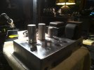
So as the title says I found this old RCA amp off the auction site and it is almost the same as the RCA SP-20 amps that I want to recreate from new parts using the original drawings. So I thought I would do a little practice by working on this and getting a better knowledge and some practice and then I can compare the amps once I finish.

This will be a recap of the RCA RS147 and the steps I do to get it up and running.

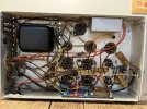
First is a bit of clean up as this thing was crusty.
133843047668351968.jpg

WIN_20260917_20_33_14_Pro.jpg


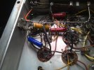
Next I am working on the replacing the can caps. I found all of these on amplified parts, and I am starting with C64A,B 100/100-50 volt. The replacement is quite a bit larger but it is a 100/100-500 volt can.

WIN_20260928_14_12_33_Pro.jpg
 
Register to hide this ad
Does the output transformer p/n match the SP-20? Just curious.

No unfortunately it doesn't, and neither does the power transformer or the choke. I thought at first these were the same, sellers on eBay are making those claims but they are clearly different.
 
Last edited:
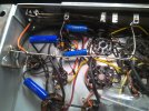
Going forward with the coupling caps. these will be caps C65, and C66, coupling the 12AU7 phase inverter, to the 6AU6 drivers. These are .10uF SoZo capacitors. These were reasonable and this amp only has as few caps so relatively easy recap.

WIN_20260928_20_01_52_Pro.jpg

As I have been going thru this, I have been checking the resistors, and also putting heat shrink on the leads and replacing some of the wire.
 
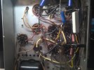
All caps completed. I have to wait a few days as I had to order some resistors to replace that special long multi resistor on the side of the chassis. I noticed a little bit of fine wire in the area where the wires terminate. Seems some of the wire wound around making up those resistors has come loose.

WIN_20260928_23_22_39_Pro.jpg

WIN_20260928_23_25_18_Pro.jpg
 
Last edited:
In old radios those are generically known as a "candohm" type. I think that was one of the brands. They are often open between a section or more. Fairly common when they go open circuit to abandon them in place and just bridge an appropriate resistor across the terminals inside.
 
In old radios those are generically known as a "candohm" type. I think that was one of the brands. They are often open between a section or more. Fairly common when they go open circuit to abandon them in place and just bridge an appropriate resistor across the terminals inside.
Yup I think if I read the drawings correctly it is spilt into three sections consisting of two 250-ohm 2-watt resistors and one 2100 ohm 3 watt resistor. I found the values but in 5 watts, which I think will work.
 
In old radios those are generically known as a "candohm" type. I think that was one of the brands. They are often open between a section or more. Fairly common when they go open circuit to abandon them in place and just bridge an appropriate resistor across the terminals inside.
In addition to this, the Candohm resistors are also know to short to the metal case which is an obvious problem. I have experienced just that with one of my Admiral televisions. It made quite a light show inside of the vintage Admiral branded 5U4G, rendering it kaput. You night consider replacing it under the chassis with discrete wirewound resistors. You can compute the wattage with Ohm's Law.
 
Does that mean yes? Would like to know what they are.
Sorry a bit slow getting back to you, I post often from at work but I don't often have the amps or gear there. And then when I got home it was need to mow the lawn, fertilized for fall, just been busy.

There are numbers on the bell ends, they don't seem to match what the drawings call out for on the RS147 prints, but I am sure these are original.

This is the power transformer.

WIN_20260929_21_43_15_Pro.jpg


And the OPT

WIN_20260929_21_43_57_Pro.jpg
 
138552 ? thats Stancor, week 52 1955 if I'm not mistaken. The other number is the RCA part number. The power transformer looks like 452525, Empire Coil from week 25 1955. Seems a bit odd to have a 6 month gap between transformer date codes but maybe they didn't build a lot of these and the transformer came from a run earlier in the year.
 
That is great info that you can share with us. The drawings are very helpful as well. I mean they even give a person the brand and part number for the Belden hookup wire.
 
In old radios those are generically known as a "candohm" type. I think that was one of the brands. They are often open between a section or more. Fairly common when they go open circuit to abandon them in place and just bridge an appropriate resistor across the terminals inside.

Finished installing all the caps and tubed up, on the variable power supply has some motorboating going on. I started right at the first line on the inputs going thru chrcking and replacing the resistors but I have not found the problem child yet. Something keeps pulling me back to thinking on that candohm resistor, wondering if I have tackled that correctly.

I removed the main ground trunk off the terminal of the Candohm resistor and terminated the wires that landed one each side of the ground leads with a 250 ohm 5 watt resistor thinking those are C99A, and C99B. then the last two tabs I landed each end of a 10watt 22k3 resistor based on the drawings C99C values. I had to abandon using the OEM candohm as the wire windings inside it were damaged.

So far the few resistors I have changed out had not drifted to far off, most were a bit higher in resistance.

WIN_20261001_22_00_54_Pro.jpg
 
Ok real close on this one, found the motor boating issue as I had my first coupling cap landed on pin 4 needed to be on pin 3. But some premonition kept me wondering if I got the resistors correct for the candohm resistor, and I must be off, The amp sounds fine, no more boating or hum but R99A resistor that I used to take the place of the third terminal of the candohm is getting very hot, and the drawing says it should be a 3 watt, and I have a 5 watt one in place. Need to figure out why that one is getting hot while R99B isn't.
 
Here is a pic of a RS-147, I circled the two terminals where the conductors go to pin 8 on the output tubes, each terminal goes to a pair of tubes by a yellow wire.

I have installed a 250 ohm resistor on each pair of tubes from the yellow leads terminating to that ground buss wire. I measured each run from where they terminate on the can cap back to where they end on the buss and they are both just shy of 250 ohms, I can't figure out why one resister is getting hot and the other isn't. On the drawings it is resistor R99A and R99B.


rs-147.jpg
 
I should add I isolated the buss from the candohm that is messed up, but it is grounded on the other end of the buss.
 
Back
Top Bottom