• The move to the new server is done. There are some software and database maintenance updates in process. This has us passing the hat around to help out. We appreciate any donations. Seriously, even a dollar helps. The payment page may be found here - https://www.audiokarma.org/support.html

Realistic 40/a Tube Amp Restoration Help

mcaddie7

Active Member
Hi all,

Looking for a schematic for this amp if anyone has it.

I have a beautiful Realistic 40/an amp that looks like it has never left a box(it has!) and the owner said it stopped working one day.

I found one of the output tubes was blown. I ordered 4 new 6BQ5s and started with my simple recap.

I replaced the 3 large gray caps (not the cans yet, one step at a time) as those are easy and out in the open.
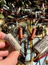
IMG_3934.jpeg

IMG_3929.jpeg

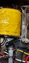
I also replaced this small cap near the transformer. This one sort of crumbled in the end that looked like it was attached to ground. Not sure if bad but replaced it with a film cap? One end to transformer, the other to ground.
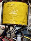
IMG_3935.jpeg

I powered it up slowly with the new tubes installed and no more than 1.0A was drawn on my meter m. Made it to 120V with no smoke and tubes glowed. However there was a loud hum in the speakers.

I was to touch the chassis but has a feeling that I should measure it for safety and lo and behold the chassis has 6VAC on it which may explain the hum.

Any pointers or schematics would be great. Owner said it worked several months ago so I believe the rectifier and everything is good but might start going point to point to make sure the right voltages are where they should be.

Thanks!
 
Register to hide this ad
The one going frm transformer to ground ideally should be a Y rated safety cap. Its going from power line to chassis, and the safety caps are designed to not fail shorted.
 
The coupling caps to the output tubes need to be replaced before it's powered up again.

Jack
 
The coupling caps to the output tubes need to be replaced before it's powered up again.

Jack
So surprisingly few caps on this piece. The only caps left to replace are the large can caps (are these the coupling caps?) and the 4 tone caps that are near the tone control. I have the equivalent caps for the large tubes, should I start there? Just weird that I was getting AC on the chasis. Could that happen if a coupling cap (tube caps) fail?
 
AC on the chassis (measured with a high impedance meter) is common in equipment powered by a 2-wire line cord. It's usually the result of power transformer leakage, or maybe there's a small capacitor or two ("death caps") connected from the AC line to chassis. Equipment like this is a safety hazard when it's surrounded by other gear that's grounded.

Jack
 
Last edited:
Measuring AC on the chassis with a high impedance meter is common in equipment powered by a 2-wire line cord. It's usually the result of power transformer leakage, or maybe there's a small capacitor or two ("death caps") connected from the AC line to chassis. Equipment like this is a safety hazard when it's surrounded by other gear that's grounded.

Jack
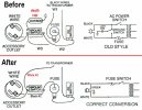
That's probably what's happening. One leg of the AC heater line (6.3VAC) may be grounded. So, the power line polarity is critical. You should probably go to a three-cord outlet line with a green line grounded to the chassis. Something like this:

three -3 prong conversion (new).jpg

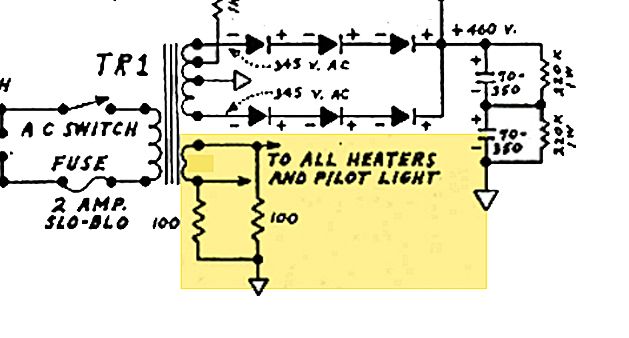
If one side of the heater line is grounded, you might consider changing it to two twisted pairs and pulling that one line off the ground. Use resistors to create an artificial center tap. It will run quieter.

e26cc44a-ebc9-465d-8772-6f047bb671d9.jpg
 
Last edited:
That's probably what's happening. One leg of the AC heater line (6.3VAC) is grounded. So, the power line polarity is critical. You should probably go to a three-cord outlet line with a green line grounded to the chassis. Something like this:

View attachment 3437548


So it does have the death cap if that black cap that connects the transformer to the chassis in my previous photo is what I think it is?

Could this explain the loud hum?

Is this safe to even touch when that 6.3v is present?

So you can see in the photo below the cap that touches to ground. The brown wires are the power cord coming into the wall. If I remove the cap, one wire from the brown plug goes to the cap / accessory outlet on the back, and I think the other brown wire from the plug goes up to the rectifier. Which direction should I hook up my three prong plug?
IMG_3952.jpeg
IMG_3951.png
 
So it does have the death cap if that black cap that connects the transformer to the chassis in my previous photo is what I think it is?

Could this explain the loud hum?

Is this safe to even touch when that 6.3v is present?

So you can see in the photo below the cap that touches to ground. The brown wires are the power cord coming into the wall. If I remove the cap, one wire from the brown plug goes to the cap / accessory outlet on the back, and I think the other brown wire from the plug goes up to the rectifier. Which direction should I hook up my three prong plug?
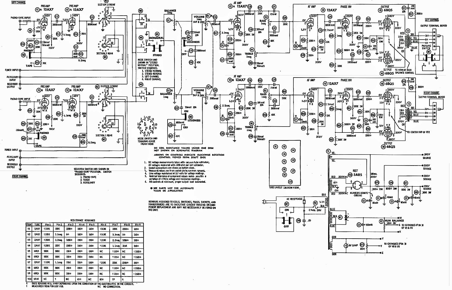
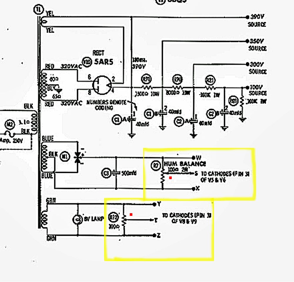
With any of these amps in question, a schematic (if possible) should be referred to. I hope that this is your amp. Please double-check to be sure.

Click on image to enlarge.

16f69760-9d16-437e-abe5-a318d0b1a3f1.jpg


I found this on the Net: Your amp seems to have HUM pots on two of the power transformer's lines.

ac393259-ef79-484b-a041-640e495c78e2.jpg


Try adjusting these to reduce the AC hum that you are getting. Eventually, you may consider a three-prong line for safety's sake.
 
Last edited:
So I don’t think that schematic is for my amp unfortunately and I can’t seem to find one.

My amp has one hum balance knob in the back. I didn’t want to touch it with a screw driver though since it has 6.3VAC on it.

I’ll send some pictures tonight of where the plug wires go and perhaps Audiokarma can help me install a three prongs

Thanks!
 

Attachments

  • IMG_3953.jpeg
    IMG_3953.jpeg
    72 KB · Views: 10
Okay I’ll replace those tonight and then ask for help with installing a three prong power cord. I’ll send pics of the power config later.
You wouldn't happen to have the schematic to your amp? Those things can answer a lot of questions. :thumbsup:

BTW... hum pots tend to be on the chassis, under the hood (so to speak).

hum pot example.jpg

Good luck!
 
Last edited:
Radio Shack Stereo 40A is covered in Sams 519-12 - I believe that's the schematic posted above.

Below 30V AC or 40V DC is not considered hazardous - shock is unlikely. A voltage from chassis to ground (even above that level) may not be hazardous if it can't supply a current above 1 mA (1 mA is considered the "startle" threshold, where a shock might make you jump or drop something). Modern safety standards allow 0.7 mA or less - a .005 uF cap will pass about 0.25 mA - might measure 60V or more if you reverse the AC plug, but still not a hazard. But of course that cap must not ever fail shorted! 'Y' type "safety" caps are tested at 1500V or more to withstand the voltage transients that are common on AC power lines.

And modern safety standards require that any accessible metal must be grounded or double insulated from the power line. The latter has to pass a breakdown test at 3000V or more. A grounded cord sometimes causes problems when connecting other devices with different grounds. But most sources won't be grounded - computer sound can be a problem, though.
 
Radio Shack Stereo 40A is covered in Sams 519-12 - I believe that's the schematic posted above.
Thanks for that message.

The owner should try adjusting the hum pots, which may solve the problem. He may also need to clean them with a contact cleaner, as God only knows how long it's been since someone used them. I like Deoxit Fader Lube on pots.

At least it's a cheap try.
 
Below 30V AC or 40V DC is not considered hazardous - shock is unlikely.
We don't know how that measurement was made, what the current capability might be, or which component(s) are the cause. We only know there's a current path between the AC line and the chassis.

Jack
 
The cap from the 117vac primary on the transformer to chassis is definitely a path. Potentially not the only one though.

Given that it was a 6vac measurement though, even if its low ohms / high current its not cause for alarm. Also fair bet if the plug was flipped over that would become a 120vac measurement to ground.

still going with the original filter cap as being why it hums, nothing to do with the voltage on the chassis or the hum pot settings.

my usual advice here is to restore things to proper operating conditions without making any modifications first, then proceed as needed. Introducing too many variables is a good path to troubleshooting hell.
 
The cap from the 117vac primary on the transformer to chassis is definitely a path. Potentially not the only one though.

Given that it was a 6vac measurement though, even if its low ohms / high current its not cause for alarm. Also fair bet if the plug was flipped over that would become a 120vac measurement to ground.

still going with the original filter cap as being why it hums, nothing to do with the voltage on the chassis or the hum pot settings.

my usual advice here is to restore things to proper operating conditions without making any modifications first, then proceed as needed. Introducing too many variables is a good path to troubleshooting hell.
I agree! I think it was you as well as Triode lover that helped me a few weeks back where I changed too many caps at once on a HK A series tube amp. However, you all taught me a lot on the topology of amps and how to troubleshoot them.

A further look last night shows that the two larger can caps are all supposed to have 2, 40uf caps. One has a cap measuring 150uf, and the other is 200uf on the other can. The concerning part is that one can has corrosion on it so it's likely you are right and these need replacing.

Ordered and waiting a few days. You all will hear from me around Monday or so. Once I get it working I'll ask for advice on where to place the three wires on a 3 pronged power cord.
 
probably very high ESR too. For reasons that I don't pretend to understand, when caps go high ESR they also tend to measure very high in value. Also possible leakage is a factor. I'm sure that would make sense if I had a couple extra brain cells to devote to learning how cap meters actually measure capacitors, but at the moment i'm lacking in spares.

anyway when they measure really goofy they are rarely any good. Visible goo leaking is never a good sign.
 
Given that it was a 6vac measurement
From which point to where? What if it was measured from the chassis to the hot side of the line? What if it's actually 114V to neutral? Until the OP defines this, no one here can say the chassis is safe to contact. Please, let's apply some scientific principles before making unfounded statements about safety.

Jack
 
doesn't really matter frankly. Unless OP touches two different points its not going to flow any current anywhere. Just while we're applying scientific principals and all.
 
Back
Top Bottom