• The move to the new server is done. There are some software and database maintenance updates in process. This has us passing the hat around to help out. We appreciate any donations. Seriously, even a dollar helps. The payment page may be found here - https://www.audiokarma.org/support.html

Realistic Minimus-1: A Small Speaker Project

Leestereo

Super Member
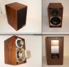
The Minimus-1 speakers are ostensibly the precursor to the very popular Minimus-7. And although they are (IMO) better sounding than its more famous successor, they are relatively unknown. Radio Shack first introduced this model in 1967 with the 40-1966 catalogue number; my set is from 1971 and its number is 40-1966A.

index.php


index.php


index.php
 
Register to hide this ad
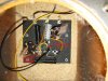
The Minimus-1 crossover consists of a 1st order low pass filter on the woofer and a 2nd order high pass filter on the tweeter; the output of the tweeter can be increased by installing the terminal bridging connector (shorts the 5 ohm resistor).

index.php


index.php


The capacitor in the tweeter high pass filter was a bipolar electrolytic type and it was replaced with a polyester film type. The original capacitors measured ~8µF with an ESR of 0.6ohm and a Vloss of 2%; the increase in capacity would lower the crossover point by ~300Hz. The replacement film capacitors measured ~6.6µF with no measurable ESR or Vloss.

index.php
 
An anti-diffraction ring made from open-cell foam was installed on the tweeter.
index.php


For the woofer, an anti-diffraction trim piece made from closed-cell foam was installed.
index.php


On the back, a foam gasket was installed; note the use of a large alnico magnet on the woofer.
index.php
 
Very nice work there. These are beautiful little speakers. This is the most information I've seen about the Minimus-1(A), and I appreciate the documentation. I have a pair of the "non-A" Minimus-1's, but the drivers and crossover are entirely different in that earlier version.

Hope it's OK to ask a barrage of small questions:
* Where did you locate schematic? Is there a similar diagram for 40-1966 version?
* Is the yellow wire + to woofer, and blue + to tweeter?
* Do you use these with strap in "increase" or "normal" position?
* Can you describe performance results of interior foam and re-cap?
* Outer trims look very good - - - definitely improves appearance, but any improvement in performance?
* Hard to tell from pics - - do woofers have inverted roll fabric surrounds?

Great project. Thx for sharing.
 
The original Minimus-1 (40-1966) are even more rare than the "A" variant! The schematic is derived from tracing the circuit and measuring the components; the yellow wire is connected to the woofer +ve terminal (which does have an inverted roll fabric surround) and the blue wire is connected to the tweeter +ve terminal. The speakers are used with the tweeter in the "normal" configuration (even then the speaker is somewhat bright sounding in my smallish living room). A comparison of the recapped/modified speaker to the stock one revealed that the recapped/modified one was smoother in the midrange (very likely due to restoring the higher design crossover point) and the upper treble sounded more extended and clearer (possibly due to the better performance of the film capacitor and the anti-diffraction treatments). With both speakers recapped/modified, the stereo image appeared wider and more focused, the latter was also noticed with mono recordings. The bass response seemed largely the same, maybe a bit better in the modified speaker (this impression could also be due to the tamer midrange response). The use of anti-diffaction treatments in more "audiophile" speaker designs seems to be well established, e.g., BBC LS3/5A, Spica TC-60, Dunlavy; the tweeter mounting plate in the Minimus-1 is a good candidate for such treatment since it has a protruding lip at its outer edge.

index.php
 
Very good report, thank you. Your schematic looks terrific, and might help me figure out the original Minimus-1, although my crossover has 2 coils, 2 resistors, and 3 caps on a small PCB.

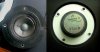
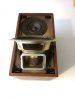
Your tweeter looks very much like the version that showed up in many Realistic speaker models. The one shown here (from an Optimus 2 speaker) does not have the upturned lip on the front plate, but otherwise appears similar. Also attached is a pic of your Minimus version that shows off the scale of the woofer magnet very well.

tweeter 2.jpg

Realistic Minimus 1 front alnico.jpg
 
Still thinking about your tweeter comments. First - - just an observation - - a 5-ohm resistor seems to be an unusually large value for an attenuation switch, but at least it's sufficiently large to create two noticeably different results. Also, I was surprised to read your comment about using these in "normal" setting and sensing the tweeter was "bright". I wonder if perhaps that is partially a result of using a film cap here and eliminating the intentional ESR of the original NPE cap? BTW, what is the type/manufacturer and voltage of that new red cap?

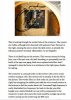
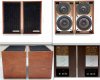
I found a few more bits in my file that I might as well post here. The first image is someone's description of this speaker - - it sounds pretty good, but this owner thought that the switch (and 5-ohm resistor) was connected to the woofer circuit. The other images are just more views of this speaker.

Minimus-1 1966A description.jpg Minimus-1 1966A.jpg Minimus-1A.jpg
 
I had a set last year that I liked and used them for front mains of my HT. I replaced them with something else then sold them for more than I paid......I prefer the Min 7Ws overall but loved the grills with the flecks in them.
 
Still thinking about your tweeter comments. First - - just an observation - - a 5-ohm resistor seems to be an unusually large value for an attenuation switch, but at least it's sufficiently large to create two noticeably different results. Also, I was surprised to read your comment about using these in "normal" setting and sensing the tweeter was "bright". I wonder if perhaps that is partially a result of using a film cap here and eliminating the intentional ESR of the original NPE cap? BTW, what is the type/manufacturer and voltage of that new red cap?

The replacement polyester film capacitor is an Illinois Capacitor 6.8uF/250V (https://www.mouser.com/ProductDetail/598-685MMR100K). Overall, in my rather "live" room, the treble response of the Minimus-1 with the film capacitor only sounded a bit brighter than the one with the stock NPE capacitor; this is not surprising since the ESR of the NPE measured ~0.6ohm; this ESR is <10% of the total resistance (7ohm) in series with the tweeter.

I found a few more bits in my file that I might as well post here. The first image is someone's description of this speaker - - it sounds pretty good, but this owner thought that the switch (and 5-ohm resistor) was connected to the woofer circuit. The other images are just more views of this speaker.

In your crossover picture, the woofer's negative tag is connected directly to the RCA jack ground via a black wire and to the speaker negative terminal via the connecting short yellow wire. Woofer -ve connection.jpg
 
Back
Top Bottom