• The move to the new server is done. There are some software and database maintenance updates in process. This has us passing the hat around to help out. We appreciate any donations. Seriously, even a dollar helps. The payment page may be found here - https://www.audiokarma.org/support.html

Brivan

Well-Known Member
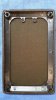
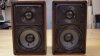
I own several pairs of Realistic Minimus 7 Walnut speakers - many of which have the dreaded broken plastic grille guides. I poked around on AK, but didn't find a mod to alleviate this perpetual problem, so I came up with one. I ordered grille guides from Parts Express, part number 260-366. Here's what I did:

Remove the speakers and insulation
01 Realistic Minimus 7 Speakers Removed (Small).jpg

Break off the remaining tabs of the existing grille guide pins.
02 Realistic Minimus 7 Grille Guide Pins Broken Off (Small).jpg

Drill a 1/16" pilot hole in the middle of each pin. When drilling holes, use the drill's lowest speed range and drill very slowly without exerting much downward force.
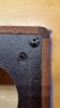
03 Realistic Minimus 7 Pilot Hole Drilled in Grille Guide Pin (Small).jpg

Drill a #7 hole in each pin. This will get the hole very close to the diameter of the existing pin. The pin might push or pull out with the drill bit. It will probably be necessary to hold the flange of the pin in place while drilling this hole, since the pin might try to spin.
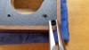
04 Realistic Minimus 7 Grille Guide Pin Being Held in Place (Small).jpg

All pins have been removed. Notice this speaker had some previous issues with the lower left-hand grille guide pin - it looks like the laminate was slightly lifted and glue was used by the previous owner to hold the pin in place.
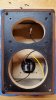
05 Realistic Minimus 7 Grille Guide Pins Drilled & Removed (Small).jpg

When enlarging the holes beyond this point, use something (tip of needle-nose pliers here) to hold down the corner of the laminate to prevent it from lifting while being drilled.
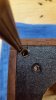
06 Realistic Minimus 7 Corner of Front Laminate Held in Place (Small).jpg

Holes have been enlarged using a two step-process - first with a 9/32 drill bit, then finishing with a 23/64 drill bit.
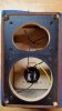
07 Realistic Minimus 7 Drilled Out for New Grille Guides (Small).jpg

Black furniture marker used to darken some of the light areas that the new grille guide flange might not cover.
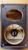
08 Realistic Minimus 7 Front Laminate Touched Up with Black Marker (Small).jpg

New grille guides installed using a small amount of adhesive to hold them in place. This is optional, as the guides will fit in pretty snugly.
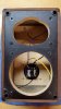
09 Realistic Minimus 7 New Grille Guides Installed (Small).jpg
 

Attachments

  • 10 Realistic Minimus 7 Grille Guide Pin Fitted Before Modification (Small).jpg
    10 Realistic Minimus 7 Grille Guide Pin Fitted Before Modification (Small).jpg
    54.5 KB · Views: 18
Register to hide this ad
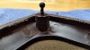
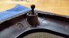
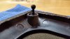
On to the grille modification. This is the grille guide pin fitted to the existing grille hole before modification. Note the flange on the pin is preventing the pin from being inserted further into the hole. The flange will need to be removed.
10 Realistic Minimus 7 Grille Guide Pin Fitted Before Modification (Small).jpg

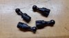
Four new grille guide pins before modification.
11 Realistic Minimus 7 Grille Guide Pins Before Modification (Small).jpg

Grille guide pins after modification. This was done on an upright belt sander.
12 Realistic Minimus 7 Grille Guide Pins After Modification (Small).jpg

Holes in the speaker grille need to be drilled out to a drill letter size "C" to accommodate the new pins. When drilling out the holes for the pins, put your finger on the front-side of the grille opposite the to-be-drilled hole. You'll feel a little dimple there. Slowly drill out the hole while feeling for the end of the drill bit. I had no issues with the bit snagging the grille cloth.

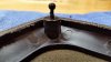
Guide pin shown glued in place. The pins fit fairly tight here, but I would recommend using adhesive on them, since the pins wobble a little due to the flat spot that's in the ribbed push-in portion.
13 Realistic Minimus 7 Grille Guide Pin Installed to Correct Depth (Small).jpg

All pins installed.
14 Realistic Minimus 7 Grille Guide Pins Installed (Small).jpg

Adhesive used. This stuff is dark in color and blends in well if there is any excess that doesn't get wiped off. Cleans up with Acetone.
15 Glue Used on Realistic Minimus 7 Grille Guides & Pins (Small).jpg

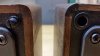
Close-Up of unmodified and modified speaker.
Realistic Minimus 7  Unmodified & Modified SPeaker Grille Guides - Close-Up (Small).jpg

Unmodified and modified speaker side by side. I like the cleaner look of the modified speaker.
Realistic Minimus 7  Unmodified & Modified Speaker Grille Guides (Small).jpg
 

Attachments

  • 13 Realistic Minimus 7 Grille Guide Pin Installed to Correct Depth (Small).jpg
    13 Realistic Minimus 7 Grille Guide Pin Installed to Correct Depth (Small).jpg
    49.1 KB · Views: 2
Last edited:
Excellent post and I'm glad you were able to come up with a solution to the problem so many folks have faced with the Minimus 7s!
 
Thanks for the post and solution. I have a pair also and had pretty much given up on a fix for the broken grill pegs.
 
Excellent post and I'm glad you were able to come up with a solution to the problem so many folks have faced with the Minimus 7s!
Thank you. If I could find a set of similar replacement guides that have a slightly-smaller receptacle diameter and a pin without a flange, that would be the cat's meow.
 
Thanks for the post and solution. I have a pair also and had pretty much given up on a fix for the broken grill pegs.
Thanks. I Iike that the pin and receptacle have their positions swapped. I think the speaker looks better without the grille pins sticking out.
 
I'm familiar with 9/32" drill bit, and 23/64", but I'm unfamiliar with the "#7" and "C" sized drill bits; am I missing something here?
 
I'm familiar with 9/32" drill bit, and 23/64", but I'm unfamiliar with the "#7" and "C" sized drill bits; am I missing something here?

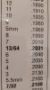
The number 7 and letter C drill bits are from a subset of drill bits that offer decimal sizes not found in a standard fractional drill bet set. From my chart, the closest standard size would be 13/64" for the number 7 and 1/4" for the letter C. Going up to 13/64" for the #7 would probably be okay, but a letter C is the perfect size for the pin and a jump to 1/4" might be a bit much (although adhesive would likely hold it in just fine). It's possible that a home improvement store would have the non-standard drill bits; otherwise they can be ordered from online sources like Grainger, McMaster-Carr or probably even Amazon.

Also, the 9/32 is just an intermediate drill size between the #7 used to remove the existing pin and the 23/64 used for the final hole size for the new receptacle. I was gradually stepping up the hole size, so something other than a 9/32 (but in the ballpark) would work fine.
20190226_122627 (Small).jpg 20190226_122701 (Small).jpg
 
Last edited:
I created a pdf document of the procedure above for my own future reference, since old guys forget stuff. I tried to attach it here, but AK complained it was too big (I don't hear that often!) so, if anyone would like a copy emailed to them, let me know and I'll send it. BTW the dim bulb tester in my sig pic is another creation of mine - made from an old decade box and some new retro-style switches and bulbs.
 
Back
Top Bottom