Some classic speakers are fabulously documented while many are shrouded in mystery. Which must frustrate hobbyists, judging by frequency these forums are peppered with unanswered requests seeking crossover data.
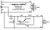
Feeding my own curiosity about vintage Optimus and Nova products has unearthed several inquiries for Nova-6 crossover info. They all lead to the same schematic. Which seems to be the lone example -- and in circulation for years. Though nicely illustrated it has a few issues that are worth addressing, especially if it's being used to guide service/repair efforts.
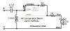
Here is the schematic as found:
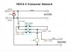
Resistors are labeled "1 watt," which is extremely unlikely. They are actually rated 5W. The author apparently misinterpreted characters printed on these resistors to mean "1W" that are actually part of the manufacturer's brand name "IWAKI."
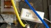
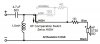
As in this other example

The HF compensation switch is labeled "DPDT," though it clearly has three position settings.
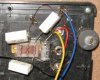
Because its two poles are strapped together, it functions electrically as a single pole switch in this circuit.
Components are drawn how they're physically oriented and connected to the switch, which makes a useful wiring diagram. But electrical pathway changes from different switch settings are not really shown at all.
Don't want to beat this up too badly -- it's a good effort -- which seems to have long served as all that was available. Any refinement offered here is built upon this prior work.
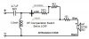
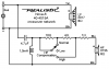
Here's a revised approach:
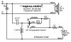
The switch doesn't switch "IN" additional series resistance for greater attenuation; it rather creates paths to bypass resistors in Normal or High settings, thus lowering series resistance attenuation.
Feeding my own curiosity about vintage Optimus and Nova products has unearthed several inquiries for Nova-6 crossover info. They all lead to the same schematic. Which seems to be the lone example -- and in circulation for years. Though nicely illustrated it has a few issues that are worth addressing, especially if it's being used to guide service/repair efforts.
Here is the schematic as found:
Resistors are labeled "1 watt," which is extremely unlikely. They are actually rated 5W. The author apparently misinterpreted characters printed on these resistors to mean "1W" that are actually part of the manufacturer's brand name "IWAKI."
As in this other example
The HF compensation switch is labeled "DPDT," though it clearly has three position settings.
Because its two poles are strapped together, it functions electrically as a single pole switch in this circuit.
Components are drawn how they're physically oriented and connected to the switch, which makes a useful wiring diagram. But electrical pathway changes from different switch settings are not really shown at all.
Don't want to beat this up too badly -- it's a good effort -- which seems to have long served as all that was available. Any refinement offered here is built upon this prior work.
Here's a revised approach:
The switch doesn't switch "IN" additional series resistance for greater attenuation; it rather creates paths to bypass resistors in Normal or High settings, thus lowering series resistance attenuation.
Last edited: