• The move to the new server is done. There are some software and database maintenance updates in process. This has us passing the hat around to help out. We appreciate any donations. Seriously, even a dollar helps. The payment page may be found here - https://www.audiokarma.org/support.html

Realistic Nova 8b Rebuild & Crossover Re-Design

Please Explain

I did the new crossover for my Optimus 5B (per the VL diagram) and listened to the results. Well, it sounded different than the original, but there was no WOW. The bass was fuller & deeper, but I attributed that to better sealing of the cab. The mids & highs didn't really sound like a speaker "transformed".
Later, I happened to come across a schematic for a three way speaker and noticed that the mid-range (bandpass) network for the VL Nova 8b mod didn't make sense.
attachment.php


What did make sense was having the 2.7uF cap as the first component, with the 2.0mH inductor as the shunt to ground after that, followed by the smaller 1.74uF cap in series and the 1.0mH inductor as the shunt to ground after that.

If you wire the mids this way, you just removed the bandpass and created a 4th order high-pass for the mids. This will allow the mids and the tweeter to operate over the same range and create lobbing effects. So, you converted the bandpass into a highpass, why? :scratch2:
 
If you wire the mids this way, you just removed the bandpass and created a 4th order high-pass for the mids. This will allow the mids and the tweeter to operate over the same range and create lobbing effects. So, you converted the bandpass into a highpass, why? :scratch2:

Maybe there's some confusion here. The diagram I put up is from your post #5 of this thread. If there is a bandpass schematic for the mids, maybe I missed it.

What I did on my speakers is arrange the x-over parts you listed for the midrange (bandpass) as the components are arranged in schematic I showed in post #236. A basic second order bandpass network for a mid.

P.S., do whatever you need to do to get better friend :thmbsp:
 
I made the changes to mine and I agree there is no wow in these speakers... the bass sounds great, but the mids and highs leave a lot to be desired.

Here's a photo of my x-over... what should I change?
 

Attachments

  • 208.jpg
    208.jpg
    87.4 KB · Views: 332
You have the woofer & tweeter networks right. Unfortunately I didn't take a pic of my updated crossover. Here is a diagram of how I hooked up my mids. It uses the same components, just arranged differently that the original schematic.
The tweeters & mids are still hooked up out of phase in relation to the woofers.

picture.php


You should notice a difference (improvement) right away.
Did you take any measures to seal the air leaks through the mids & tweeter cups or the RCA jack in the terminal plate?
 
My Optimus 5b mod

Here is a link to the album of the work I did to my Optimus 5b's. I must say they sound pretty good now :banana:. Across the board, they do everything better than the stock speaker. Enough so that I'm actually considering putting some better quality caps in there to see if I can take it up another notch :scratch2:

Many thanks to videolady for the crossover work necessary to transform these speakers :thmbsp:.

http://www.audiokarma.org/forums/album.php?albumid=1219

I'll post a few pics when the work on the cabinets is done. Right now it's just too :tears:
 
The crossover you copied is based on the schematic shown in post #5 of this thread. The problem is that the network for the mids is wrong. The problem is that there is still nothing to filter the high frequencies out of the mids. In this configuration, the mids are doing the same thing as in the original crossover. That is, playing high frequencies along with the tweeter.

There must have been an error in the layout of the schematic in post #5. Look at any schematic for a second order, three-way crossover (in a book, on the web, etc), and it will look like the diagram I put up in post #246.

Here's how you prove it to yourself. You've already got one crossover built. Go ahead and install it in a speaker. When you get the rest of your parts in, assemble it with the midrange crossover wired as shown in post #246 and install that in the other speaker and compare.
 
Circuit Diagram

The crossover you copied is based on the schematic shown in post #5 of this thread. The problem is that the network for the mids is wrong. The problem is that there is still nothing to filter the high frequencies out of the mids. In this configuration, the mids are doing the same thing as in the original crossover. That is, playing high frequencies along with the tweeter.

There must have been an error in the layout of the schematic in post #5. Look at any schematic for a second order, three-way crossover (in a book, on the web, etc), and it will look like the diagram I put up in post #246.

Here's how you prove it to yourself. You've already got one crossover built. Go ahead and install it in a speaker. When you get the rest of your parts in, assemble it with the midrange crossover wired as shown in post #246 and install that in the other speaker and compare.

The circuit I posted is correct, it is a band pass for the mids and it is a second order filter. I don't know where you keep stating it's wrong. You are guessing at what you have done and don't know how to read the diagram if you state it is not a second order band pass. Sorry to be so blunt, but you are misleading people about the design. Look at the transfer function on the first page if you what to see the transfer voltage. You are doing your work by ear and are wrong. You may prefer the sound of what you have done but it will not produce a flat response if the drivers I listed are used. Also, this speaker is designed to be up off the floor about 8 inches and should not be pushed into a corner. Each can do as they will with their own speakers but the diagram is right and the mid section is a second order band pass. That's the bottom line. Also, the image you posted is the same thing. So what are you saying??
 
Last edited:
Proof of Crossover Design

I removed this post as I had made a mistake as pointed out by RayW. The reply was not so good and was from a mistake I made so I removed it. SORRY....


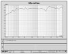
PLEASE pay no attention to the graphs in this one post as they are in error. If you know how I can remove them, please let me know.
 

Attachments

  • spl.jpg
    spl.jpg
    127.4 KB · Views: 131
  • volts.jpg
    volts.jpg
    130 KB · Views: 122
  • circiut.jpg
    circiut.jpg
    133.6 KB · Views: 188
Last edited:
You sure, VL? Running just the midrange portion of Ricky's XO (the circuit you linked in #251) in Micro-Cap shows a bandpass centered at about 3.8kHz.

Note: it won't be exact because I was lazy and just used a plain resistor for the load, but I don't see where it will pass full voltage at 120Hz.
 

Attachments

  • Nova mid XO ricky.jpg
    Nova mid XO ricky.jpg
    32.4 KB · Views: 68
Things to Check

I made the changes to mine and I agree there is no wow in these speakers... the bass sounds great, but the mids and highs leave a lot to be desired.

Here's a photo of my x-over... what should I change?

1..Did you check your tweeter and midrange to make sure the stock #s match what I listed on page one?

2..Did you check your tweeter and see that on an ohm meter it shows around 7 ohms? Did you check the mids in series and see that they show around 7 ohms?

3..Did you check the polarity at the driver terminals to make sure they are correct. Your crossover looks great and is wired correct!!

4..Are you running these tone flat. Loudness turned off and bass and treble in the mid position?

5..Have you moved them out of the corner and raised them off the floor 6 to 8 inches.

These are things to do/check. Hope this helps.
 
Xover Questions

You sure, VL? Running just the midrange portion of Ricky's XO (the circuit you linked in #251) in Micro-Cap shows a bandpass centered at about 3.8kHz.

Note: it won't be exact because I was lazy and just used a plain resistor for the load, but I don't see where it will pass full voltage at 120Hz.

I am very, very sure. The drivers are reactive loads and you must be using a fixed resistor. I did impedance sweeps of the drivers in the cabinet. The software and hardware I use is into the thousands of dollars and is an industry standard. This is where a basic knowledge causes some issues. If you would like to test this. Do it his way and turn up the volume one time for 30 seconds and let us all know what happens.
 
If you have the inductance of the midrange coil, please post it and I'll add it to the model.

In your voltage TF plot for the midrange the legend shows "spliced at 250.000". What is spliced?

edit: Check your inductor values as run. The units in the crossover you posted show as "1" and "2" without a multiplier (milli). Do you have the units set to default to mH? If I run the sim with 1H and 2H for the inductors instead of 1mH and 2mH then I get a response very close to the blue line in your graph.
 
Crossover Corrections

If you have the inductance of the midrange coil, please post it and I'll add it to the model.

In your voltage TF plot for the midrange the legend shows "spliced at 250.000". What is spliced?

edit: Check your inductor values as run. The units in the crossover you posted show as "1" and "2" without a multiplier (milli). Do you have the units set to default to mH? If I run the sim with 1H and 2H for the inductors instead of 1mH and 2mH then I get a response very close to the blue line in your graph.

Very good call RayW. I went back and checked and as you said, I found that they were marked in H instead of mH. I have no problem saying I am wrong when I make a mistake and that was a mistake. Posted are the corrections. It should not blow the drivers if you use what RickeyM posted as his mods. It does however, still create a hole of 10db around 2.6khz and a large peak of 8db around 4khz. I have 3 pair of these running with the new crossovers and have measured each pair and the sweeps are like the one posted on page one. As I stated each can do as they want, they are your speakers! I prefer the flat response and summation of a more linear speaker. To each his own! Also, Spliced refers to a ground plane from 250hz down and a gated sweep for the highs from 250hz up of the woofer.
 

Attachments

  • spl2.jpg
    spl2.jpg
    118.2 KB · Views: 177
  • volts2.jpg
    volts2.jpg
    121.2 KB · Views: 161
  • circuit2.jpg
    circuit2.jpg
    130.4 KB · Views: 579
Last edited:
I'm currently driving my Optimus 5b's with a Yammie MX-830 power amp (quite beefy) and they've been cranked up a few times since the work has been done. Happy to say they're alive and well. Nor have I heard a severe dip centered between 1600hz and 6000hz. Such a broad and deep dip would easily disernable even without measuring device, no?

You can read a crossover schematic and so can I. How about you show me what portion of the network of the diagram you posted (post #5) for the midrange, filters the highs out of the midranges.

Actually, in looking at that schematic, if the inductor labeled L3 was in the circuit between capacitor C3 and inductor L2 wouldn't that be a proper bandpass?

OK, I was typing up my post and you got your reply to Ray in before I posted. Just out of curiosity, have you run the original (post 5) crossover with the inductors set at mH instead of H ? I still believe the somewhat lackluster results I got was from the mids still playing up into the tweeter region like the original Nova/Optimus crossover design. Another question. The dip and peak you speak of in the midrange. Would reversing the polarity of the mids (back to in-phase with the woofers) fix this? You see, I prefer the flat response and summation of a more linear speaker too.
 
Last edited:
Crossovers

I'm currently driving my Optimus 5b's with a Yammie MX-830 power amp (quite beefy) and they've been cranked up a few times since the work has been done. Happy to say they're alive and well. Nor have I heard a severe dip centered between 1600hz and 6000hz. Such a broad and deep dip would easily disernable even without measuring device, no?

You can read a crossover schematic and so can I. How about you show me what portion of the network of the diagram you posted (post #5) for the midrange, filters the highs out of the midranges.

Actually, in looking at that schematic, if the inductor labeled L3 was in the circuit between capacitor C3 and inductor L2 wouldn't that be a proper bandpass?

OK, I was typing up my post and you got your reply to Ray in before I posted. Just out of curiosity, have you run the original (post 5) crossover with the inductors set at mH instead of H ? I still believe the somewhat lackluster results I got was from the mids still playing up into the tweeter region like the original Nova/Optimus crossover design. Another question. The dip and peak you speak of in the midrange. Would reversing the polarity of the mids (back to in-phase with the woofers) fix this? You see, I prefer the flat response and summation of a more linear speaker too.

I did make some corrections to what I posted as pointed out by RayW. If you look at the circuit there is a CL and also a LC. Just because the two are not layed out as a standard sample circuit does not mean it's not there. If you look at the transfer function graph, how can you question this. Seems RayW has the software as well to model this. RayW, can you model the transfer function of the midrange section I have posted? The voltage on the transfer function graph shows the band pass operation and the voltage cut off on both sides of the selected frequency. I am sorry you don't see it but it is there. I don't know where you are located, but I will be glad to test you speakers for free if you want to come to the lab. I also guess they could of changed the production of the drivers at some time as well. The one sure way to know would be to test them. Didn't mean to get you rattled but you did sort of slam the diagram and said the band pass is not there and it is. It's just not the way you want to see it. The first series C and the only parallel L is the high pass. The first series L and the only parallel C is the low pass.
 
Last edited:
Crossover Questions

RickeyM said:
OK, I was typing up my post and you got your reply to Ray in before I posted. Just out of curiosity, have you run the original (post 5) crossover with the inductors set at mH instead of H ? I still believe the somewhat lackluster results I got was from the mids still playing up into the tweeter region like the original Nova/Optimus crossover design. Another question. The dip and peak you speak of in the midrange. Would reversing the polarity of the mids (back to in-phase with the woofers) fix this? You see, I prefer the flat response and summation of a more linear speaker too.

I did flip it back in phase and it gets a little better but still shows a bump of around 5db and a dip of about 6db, but it does make it better.

I did design the speaker to produce a flat response in an anechoic room. So, it should be off the floor around 8" and not in a corner. The amp should also be set flat (no boost) and the loudness turned off. I am sure you know that but this is more for the ones that may not.
 
Last edited:
Well, I did slam your first schematic because I looked at it and saw the larger inductor & cap in the circuit after the smaller cap & inductor and thought that couldn't be right. I'll re-do the x-o's and give it an honest listen. BTW, did you notice any burn-in of the new crossovers? Also did you take any measures to further seal the cabinets? As they come, I discovered they aren't totally sealed at the mids/tweeter cups and through that RCA jack in the terminal plate.

I have the speakers about 4" off the floor now but I have some nifty stands sold by Radio Shack "back in the day" and they should be the right height :thmbsp:
 
Back
Top Bottom