• The move to the new server is done. There are some software and database maintenance updates in process. This has us passing the hat around to help out. We appreciate any donations. Seriously, even a dollar helps. The payment page may be found here - https://www.audiokarma.org/support.html

Realistic SA-2001 Relay not clicking on.

chosen

New Member
My SA-2001 has been showing the age of its caps/resistors and connections. Over the past 5 months or so I've had to leave my amp on 24/7 due to the relay sluggishly/not at all powering on. I did another once over with detoxit yesterday to rectify the issue but it seems like I might have to replace components.

Does anyone have any advice about the speaker protection relay functionality?
I had read that it wont power on if there is a short in the system. The available schematic .pdf is poorly scanned so it isn't of much help.

The relay is uy4-24us-40l. I can't find a replacement for the life of me.
 
Register to hide this ad
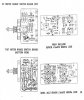
You are correct the schematic is pretty poor, but still usable, you just can't read the part designation numbers. Near the bottom is the power supply/regulator and protection schematic. Providing there are no problems with either channel, mainly high DC voltage on the outputs we can narrow it down to the actual relay circuit. There are two DC voltages involved, the DC voltage for the relay coil itself and the DC voltage that energizes it. On the secondary of the power transformer there is lead directly to the left of the center tap of the upper secondary that goes up and to the left to the third terminal from the left on the protection circuit board. This is what makes the DC voltage for the protection circuit. It goes to the anode of the diode connected to the third terminal then gets filtered by the capacitor near the bottom furthest to the left, that capacitor could be dead. Another capacitor which provides the initial time delay is straight down from that first diode, this capacitor could be dead also. Now the voltage for the relay coil is coming directly from the main + filter capacitor, I would suspect that voltage is OK as it also provides voltage to the + regulator and you would probably have more problems than you do. If this is not clear enough just replace the electrolytic capacitors on that board.

To check for DC voltage on the outputs measure the voltage on the two upper left terminals on that circuit board.

Craig
 
Is the power protection board the same board in which the relay resides? Also, kinda a noob at using multimeters in such a congested type of board layout. I ground out on the casement and use the red lead to test for DC voltages on components that are closely tied to the transformer?
 
g41OyXp.jpg
7yWolTK.jpg
 

Attachments

  • mainampboardSA-2001.jpg
    mainampboardSA-2001.jpg
    57.3 KB · Views: 11
I ordered 2 new audio transistors, tons of resisters, electrolytic caps. (not the big boys, they are $16 each)
 
TiaV6fe
gFsqeLT
QcB6dco
I tested the overheat fuse for continuity, as well as the relay and they both had continuity. Somehow I ordered the wrong audio amp 2SD733 instead of 2SC116. D: I'm still hunting for a culprit that was causing the short fault speaker protection from the relay to kick in. If anybody has any ideas i'd love to hear them. I have the amp almost completely apart, labeled, diagrammed in preparation of replacing all of the caps which are now 48 years old. And possibly resistors. I havent seen any bloated, leaking caps, nor scorch marks or lifted traces/bad solder joints. IMG_20180810_183351909.jpg IMG_20180810_183347849.jpg IMG_20180810_183409550.jpg
 
On the protection/regulator schematic there are two inputs in the upper left corner of the schematic. Those two inputs are the outputs of each channel, these inputs should be close to 0VDC, if they are the power amplifiers should be fine and your problem is a faulty protection circuit. That's all I can tell from the blurry schematic.

Craig
 
Well, I found a few corroded transistor leads, lifted traces, cold solders, and degraded resistors. Ive got all the boards out and I am in the process of recapping, replacing diodes, transistors, resistors and the like as well as bulking up poor solder joints.
 
chosen Welcome to AK. Would like to see a close up pic of the relay top and bottom of the PCB.. Possible to see who made it and figure out a replacement knowing the footprint of the relay. And the voltages around the protection circuit if known.
 
You are correct the schematic is pretty poor, but still usable, you just can't read the part designation numbers. Near the bottom is the power supply/regulator and protection schematic. Providing there are no problems with either channel, mainly high DC voltage on the outputs we can narrow it down to the actual relay circuit. There are two DC voltages involved, the DC voltage for the relay coil itself and the DC voltage that energizes it. On the secondary of the power transformer there is lead directly to the left of the center tap of the upper secondary that goes up and to the left to the third terminal from the left on the protection circuit board. This is what makes the DC voltage for the protection circuit. It goes to the anode of the diode connected to the third terminal then gets filtered by the capacitor near the bottom furthest to the left, that capacitor could be dead. Another capacitor which provides the initial time delay is straight down from that first diode, this capacitor could be dead also. Now the voltage for the relay coil is coming directly from the main + filter capacitor, I would suspect that voltage is OK as it also provides voltage to the + regulator and you would probably have more problems than you do. If this is not clear enough just replace the electrolytic capacitors on that board.

To check for DC voltage on the outputs measure the voltage on the two upper left terminals on that circuit board.

Craig


i just replaced 99%; ( from mouser),of parts due to rust damage Only on one channel. i went ahead and replaced both sides.No cheap parts were used. I turn the unit on and it lights up, the relay does not click. I need suggestions on where to look please. i checked the resistors it mentioned and all were OK. relay is new.
 
i just replaced 99%; ( from mouser),of parts due to rust damage Only on one channel. i went ahead and replaced both sides.No cheap parts were used. I turn the unit on and it lights up, the relay does not click. I need suggestions on where to look please. i checked the resistors it mentioned and all were OK. relay is new.
WOULD YOU SEND ME A LIST OF THE PARTS YOU PURCHASED FROM MOUSER PLEASE. i HAVE ONE NEW UNIT WITH PARTS REPLACED EXCEPT TRANSISTORS. ONE SIDE POPS WHEN BEING USED.
 
i just replaced 99%; ( from mouser),of parts due to rust damage Only on one channel. i went ahead and replaced both sides.No cheap parts were used. I turn the unit on and it lights up, the relay does not click. I need suggestions on where to look please. i checked the resistors it mentioned and all were OK. relay is new.
Can you please tell me which relay you used? I understand there is no current drop in replacement available
 
Back
Top Bottom