• The move to the new server is done. There are some software and database maintenance updates in process. This has us passing the hat around to help out. We appreciate any donations. Seriously, even a dollar helps. The payment page may be found here - https://www.audiokarma.org/support.html

Realistic STA-2000 Protection Relay Voltages... Anyone?

polypetalous

Super Member
I love my vintage Realistic setup.. but, boy does it like to keep my guessing.

Realistic STA-2000
Been having intermittent Speaker Protection Relay issues...
About once every couple of weeks, I will encounter an issue where the protection relay will engage/disengage say every 5-minutes or so. But every other time the Receiver will run flawlessly for hours, days etc.

I have really wanted to check voltages at the protection boards when the relay WONT engage, but every time I try to take the unit apart to check, by the time I get there the relay has re-engaged and is working.

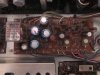
But that being said, when the unit is functioning here are the voltages I get on the protection board at (what I think) are the in voltage and out voltage pins of the protection board.

Protection Board
Pin #1 - Right Channel IN ~16 DC Volts
Pin #2 - Left Channel IN ~ 9 DC Volts
Pin #3 - Right Channel OUT ~10 DC Volts
Pin #4 - Left Channel OUT ~6 DC Volts

I suspect BOTH L & R In/out should be the same. And again the above readings was while the unit was functioning.
So my initial thought is RIGHT AMP board has gone awry and is probably showing HIGHER voltage when the relay disengages.

But I honestly DON'T know what the correct voltages here should be.
I dont know if this is a AMP board recap, a Protection board recap, power supply recap or the whole enchilada, or something else all together.

Would love anyones thoughts, input, anecdotes etc.

Thanks in advance.

Ben
 
Register to hide this ad
Pins 3 and 4 are the amplifier outputs/ protection inputs and both should be ZERO VDC. VR501 and 502 are the DC Offset adjustments, whether they'll compensate for that much offset is doubtful. The input diff transistors may have drifted over the years, TR501-504.

Craig
 
Pins 3 and 4 are the amplifier outputs/ protection inputs and both should be ZERO VDC. VR501 and 502 are the DC Offset adjustments, whether they'll compensate for that much offset is doubtful. The input diff transistors may have drifted over the years, TR501-504.

Craig

Craig,
Thank you for the response.
I see that the VR501 / VR502 and TR501-504 you reference are on the AMP boards... So I can gather that your initial impression at least is that the AMP boards are the issue?
Do you think (I know this is guessing at this point) this is possibly transistor issue? or could it be caused by leaky capacitors?

I guess the real question.. How am I best to proceed/troubleshoot form here?
This is a completely unrestored unit, so I know its anyone's guess, but I am dedicated to this unit so Im up for anything here...
Thanks again for the reply/help.

Ben
 
So DC offset is OK unless it's intermittent. Have you tried to induce the problem at all?

Craig

No not really.
This problem first happened say two-weeks then didn't happen again after repeated use for hours.
Then yesterday it happened again, and while the relay was tripped I tried to get the lid off to check what was happening.
I slightly tapped on the relay case and the relay opened and the receiver worked for the rest of the evening.

I did try changing source inputs... cranked the volume, not crazy high but higher than my normal listening and nothing caused the relay to shut off.
The pin reading above, I took multiple times and they were consistent in the readings I listed.

How else might I induce this?

Ben

edit: not sure if its important, but I HAVE taken the cover off the relay and cleaned the contacts before... a couple of years ago.
I'd love to think its just a relay problem, but I highly doubt that.. right?
 
If the relay is energizing and de-energizing then it's just doing what it's told by the protection circuitry. C601 is the filter capacitor for the protection circuitry power supply, it's relatively small on purpose so if it's on it's way out that might do it. When the signal comes back on is there a time delay, like when you first turn it on, or does the signal go in and out without delay. Another possibility are capacitors C603 and 604, they form a low pass filter that "should" filter out the audio so the DC detector only responses to very low frequencies or DC. If they are on their way out they won't filter the audio and the DC detector will respond to audio. The only other capacitor in the circuit is C602 and that is part of the time delay.
 
I forgot about the over-current adjustment, VR603, if that trim pot hasn't moved in years the contacts could be oxidized and cause who knows what kind of problems. Mark the pot., then try exercising it end to end several times and reset to the marked position.
 
If the relay is energizing and de-energizing then it's just doing what it's told by the protection circuitry. C601 is the filter capacitor for the protection circuitry power supply, it's relatively small on purpose so if it's on it's way out that might do it. When the signal comes back on is there a time delay, like when you first turn it on, or does the signal go in and out without delay. Another possibility are capacitors C603 and 604, they form a low pass filter that "should" filter out the audio so the DC detector only responses to very low frequencies or DC. If they are on their way out they won't filter the audio and the DC detector will respond to audio. The only other capacitor in the circuit is C602 and that is part of the time delay.

As I recall, as the Relay engages/disengages the signal (music) reaction is near instantaneous, no real time delay. and in fact there was a couple of times (rarer) that there was a click-click with seemingly NO interruption to the signal.

Sounds like i need to check some components on the Protection Board, I am trying to avoid the "shotgun method" of recapping.
I have somehow kept this receiver going for years with little to no experience in electronics repair... but boy sure have learned a lot!
 
I forgot about the over-current adjustment, VR603, if that trim pot hasn't moved in years the contacts could be oxidized and cause who knows what kind of problems. Mark the pot., then try exercising it end to end several times and reset to the marked position.

Now my schematics are a bit fuzzy...
But I have a pre Serial#18757 unit, so my protection board only has TWO VRs, which look like VR601 & VR602.... its seems after Serial#18757 they added VR603 & VR604 to the protection board...

Not sure you have the same documents I do.. but is that correct?
 
These must be different versions of the unit. My schematic has 31-2075 as a stock number for the STA-2000. Where did you get your schematic? Mine is from HFE.

OK, I found that board layout in the service manual but no schematic for it.
 
Last edited:
These must be different versions of the unit. My schematic has 31-2075 as a stock number for the STA-2000. Where did you get your schematic? Mine is from HFE.

OK, I found that board layout in the service manual but no schematic for it.


Yeah I suspect we are looking at the same documents, as I believe there is only ONE STA-2000 Service Manual around the web... its marked on the front page as "Sams Modular Hi Fi Components."

And it really never occurred to me but you are right on the overall system schematic, it has the "Other board" with the VR603 shown.

This makes mine an early production STA-2000, yay me...

Last night while I was taking pictures of my protect board I was trying everything in my power to get the Protect Relay to disengage...but unit stayed solid and functional ALL night.


Again, thank you for all the responses and effort here, it has been greatly appreciated.
Ben
 
Back
Top Bottom