• The move to the new server is done. There are some software and database maintenance updates in process. This has us passing the hat around to help out. We appreciate any donations. Seriously, even a dollar helps. The payment page may be found here - https://www.audiokarma.org/support.html

Realistic STA-2000D: Turns On but No sound

Juan-Jose

Active Member
I was able to grab this massive Realistic STA-2000D in a gear lot with other stuff.
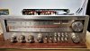
20230104_115549_HDR.jpg

Unit turns On but there's No sound.

I feel an instant "click" when it turns On (there's no delay like the usual protection relay clicking out - this one clicks right away and the "click" is hardly perceptible).

Unit is currently connected to a Dim-bulb (75W) Tester, the DBT goes into a variac (set to 117VAC). DBT lights up very bright and then goes faint as expected.
WhatsApp Image 2023-01-04 at 1.05.04 PM.jpeg

Upon initial visual check, nothing seems to be burnt.
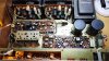
20230104_115559.jpg

Connected Pre/Main jumpers, same results.

Connected directly into wall outlet, same results.

Tried all inputs (Aux1, Aux2, Phono, AM, FM and Main In, same results. While changing stations in FM, the FM tuning meter seems to change (like it is picking up stations).

Tried all outputs (Channel A, Channel B, Pre Out and Headphones), same results. Power meters never moved.

All fuses tested Ok outside.

Removed all four Output transistors, same results: just an instant but hardly perceptible "click", not the usual relay click. Installed Output transistors back.

Service Manual can be found here.
Schematic diagram can be found here.
Source: Realistic STA-2000D AM/FM Stereo Receiver Manual | HiFi Engine

Any guidance will be much appreciated, PLEASE :(.
 
Register to hide this ad
just saw a thread this morning on a realistic. members there spoke of issues with the switches and bypassing them.
 
It looks like there are 22 pins on the power supply. Using your multimeter, clip the negative lead to the chassis and the positive to each of the 22 pins one at a time. Set your meter to AC for pins 1-8 and DC for pins 9-22 and reply back with your voltages. Do not touch your positive probe to anything else inside the stereo! If you don't have mini grabbers you can use masking tape to insolate all but the tip of your probe.
 
If I remember correctly you should get an almost instant click when pushing the power button, then a secondary click out of protection a few seconds later. Very possible it's staying in protection.
 
It looks like there are 22 pins on the power supply. Using your multimeter, clip the negative lead to the chassis and the positive to each of the 22 pins one at a time. Set your meter to AC for pins 1-8 and DC for pins 9-22 and reply back with your voltages. Do not touch your positive probe to anything else inside the stereo! If you don't have mini grabbers you can use masking tape to insolate all but the tip of your probe.

Pin 1: 13.68 VAC
Pin 2: 13.78 VAC
Pin 3: 23.89 VAC
Pin 4: 0.0066 VAC
Pin 5: 24.01 VAC
Pin 6: 7.04 VAC
Pin 7: 6.94 VAC
Pin 8: 0.0013 VAC
Pin 9: 7.73 VDC
Pin 10: 7.73 VDC
Pin 11: 0 VDC
Pin 12: -19.09 VDC
Pin 13: -14 VDC
Pin 14: 0 VDC
Pin 15: 18.78 VDC
Pin 16: 13.29 VDC
Pin 17: 13.13 VDC
Pin 18: -0.003 VDC
Pin 19: 0 VDC
Pin 20: 0 VDC
Pin 21: 0 VDC
Pin 22: 29.46 VDC
 
If I remember correctly you should get an almost instant click when pushing the power button, then a secondary click out of protection a few seconds later. Very possible it's staying in protection.
Exactly what seems to be happening.
 
It looks like there are 22 pins on the power supply. Using your multimeter, clip the negative lead to the chassis and the positive to each of the 22 pins one at a time. Set your meter to AC for pins 1-8 and DC for pins 9-22 and reply back with your voltages. Do not touch your positive probe to anything else inside the stereo! If you don't have mini grabbers you can use masking tape to insolate all but the tip of your probe.

Power supply readings. Connected directly to the wall, no variac/dbt:

Pin 01: 16.21 VAC
Pin 02: 16.33 VAC
Pin 03: 28.27 VAC
Pin 04: 00.01 VAC
Pin 05: 28.29 VAC
Pin 06: 8.03 VAC
Pin 07: 8.20 VAC
Pin 08: 0.01 VAC
Pin 09: 9.82 VDC
Pin 10: 9.83 VDC
Pin 11: 0.00 VDC
Pin 12: -24.1 VDC
Pin 13: -17.6 VDC
Pin 14: 0.00 VDC
Pin 15: 23.90 VDC
Pin 16: 16.82 VDC
Pin 17: 13.37 VDC
Pin 18: 0 VDC
Pin 19: 0 VDC
Pin 20: 0 VDC
Pin 21: 0 VDC
Pin 22: 36.7 VDC
 
These all look good. It sounds like the stereo is stuck in protection. You might want to focus on the protection and amp boards.
 
Power supply readings. Connected directly to the wall, no variac/dbt:

Pin 01: 16.21 VAC
Pin 02: 16.33 VAC
Pin 03: 28.27 VAC
Pin 04: 00.01 VAC
Pin 05: 28.29 VAC
Pin 06: 8.03 VAC
Pin 07: 8.20 VAC
Pin 08: 0.01 VAC
Pin 09: 9.82 VDC
Pin 10: 9.83 VDC
Pin 11: 0.00 VDC
Pin 12: -24.1 VDC
Pin 13: -17.6 VDC
Pin 14: 0.00 VDC
Pin 15: 23.90 VDC
Pin 16: 16.82 VDC
Pin 17: 13.37 VDC
Pin 18: 0 VDC
Pin 19: 0 VDC
Pin 20: 0 VDC
Pin 21: 0 VDC
Pin 22: 36.7 VDC

Those look like solid voltages. Lucky you. I have a STA-2000 on the bench. It started off with no sound. 9 times out of 10 its dirty knobs and buttons, switches etc....
Regardless all of those need a good cleaning. Internally there are quite a few Sanyo caps that need to be 86'ed as well and a large amount of 2SA750's These
won't necessarily cause what you are experiencing but will come back to bite you later.
 
Last edited:
Power supply readings. Connected directly to the wall, no variac/dbt:

Pin 01: 16.21 VAC
Pin 02: 16.33 VAC
Pin 03: 28.27 VAC
Pin 04: 00.01 VAC
Pin 05: 28.29 VAC
Pin 06: 8.03 VAC
Pin 07: 8.20 VAC
Pin 08: 0.01 VAC
Pin 09: 9.82 VDC
Pin 10: 9.83 VDC
Pin 11: 0.00 VDC
Pin 12: -24.1 VDC
Pin 13: -17.6 VDC
Pin 14: 0.00 VDC
Pin 15: 23.90 VDC
Pin 16: 16.82 VDC
Pin 17: 13.37 VDC
Pin 18: 0 VDC
Pin 19: 0 VDC
Pin 20: 0 VDC
Pin 21: 0 VDC
Pin 22: 36.7 VDC
Pin 18 should probably be around 12VDC, I didn't trace it, but that's probably just for the tuner.

There's a separate bridge rectifier for the output stage. I'd recommend checking that::
upload_2023-1-7_11-1-2.png
 
Back
Top Bottom